
Modular decking tile

a module and decking technology, applied in the field of modules, can solve the problems of large amount of timber required, high risk, and large platform area, and achieve the greatest degree of versatility in deck configuration, and reduce the risk of slipping on the upper surfa

Inactive Publication Date: 2005-09-08
SMART GREGORY JAMES +2
View PDF17 Cites 31 Cited by
  • Summary
  • Abstract
  • Description
  • Claims
  • Application Information

AI Technical Summary

Benefits of technology

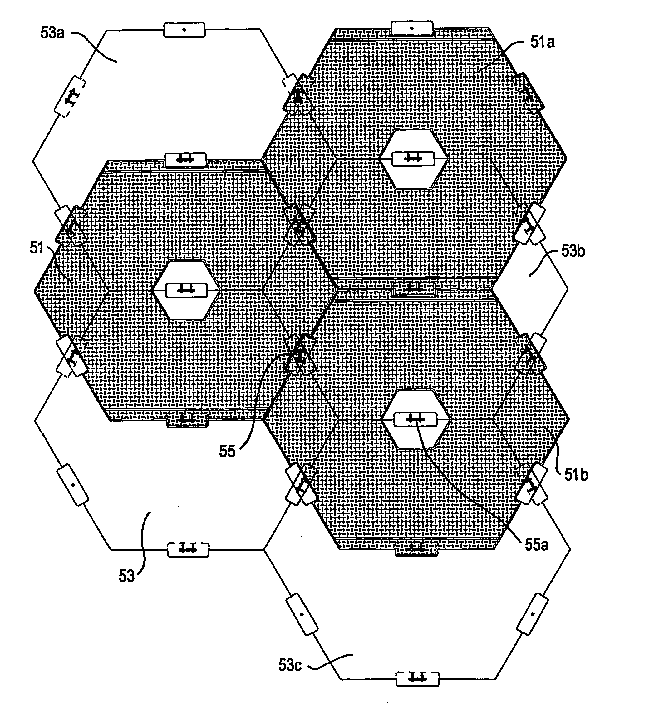
[0009] The tile may have a planar polygonal upper surface. The upper surface forms the surface of the deck that is subjected to downward and lateral forces from traffic including pedestrian and vehicular traffic when in use. The upper surface may include friction-enhancing means such as a textured or roughened surface treatment, and / or a plurality of raised lugs such as a chequerplate pattern so as to reduce the risk of slipping on the upper surface. The upper surface may be a regular polygonal shape such as a triangle, square, pentagon or octagon, but preferably is hexagonal in shape. It is considered that a hexagonal shape allows the greatest degree of versatility in deck configuration and also provides lo optimal rigidity and interfile connection to create the deck structure. This is because each tile within the deck structure is held in place by six adjacent tiles.

Problems solved by technology

In many cases the working platform area is of considerable size, so large amounts of timber are required.
Not only is this process labor intensive and high risk, it is also destructive to a broad perimeter of vegetation surrounding the actual working area and can be regarded as an environmentally unsound practice.
Once drilling operations cease, the cut timber is not of economic value so it is left in situ and gravel and timber are required to be excavated and removed from the location.
Despite any restoration works to the area, the native flora is likely to take decades to regenerate and recover.
In mining locations where there is no local supply of forest timber from which to make a suitable working platform, companies have been known to airlift in loads of gravel for foundations, clearly at considerable expense.
Again, although material is generally not recovered for re-use after the site is abandoned, it may need to be excavated and removed.
Mining operations place high demands on the working platform.

Method used


Image

  • Modular decking tile
  • Modular decking tile
  • Modular decking tile

Examples


Embodiment Construction

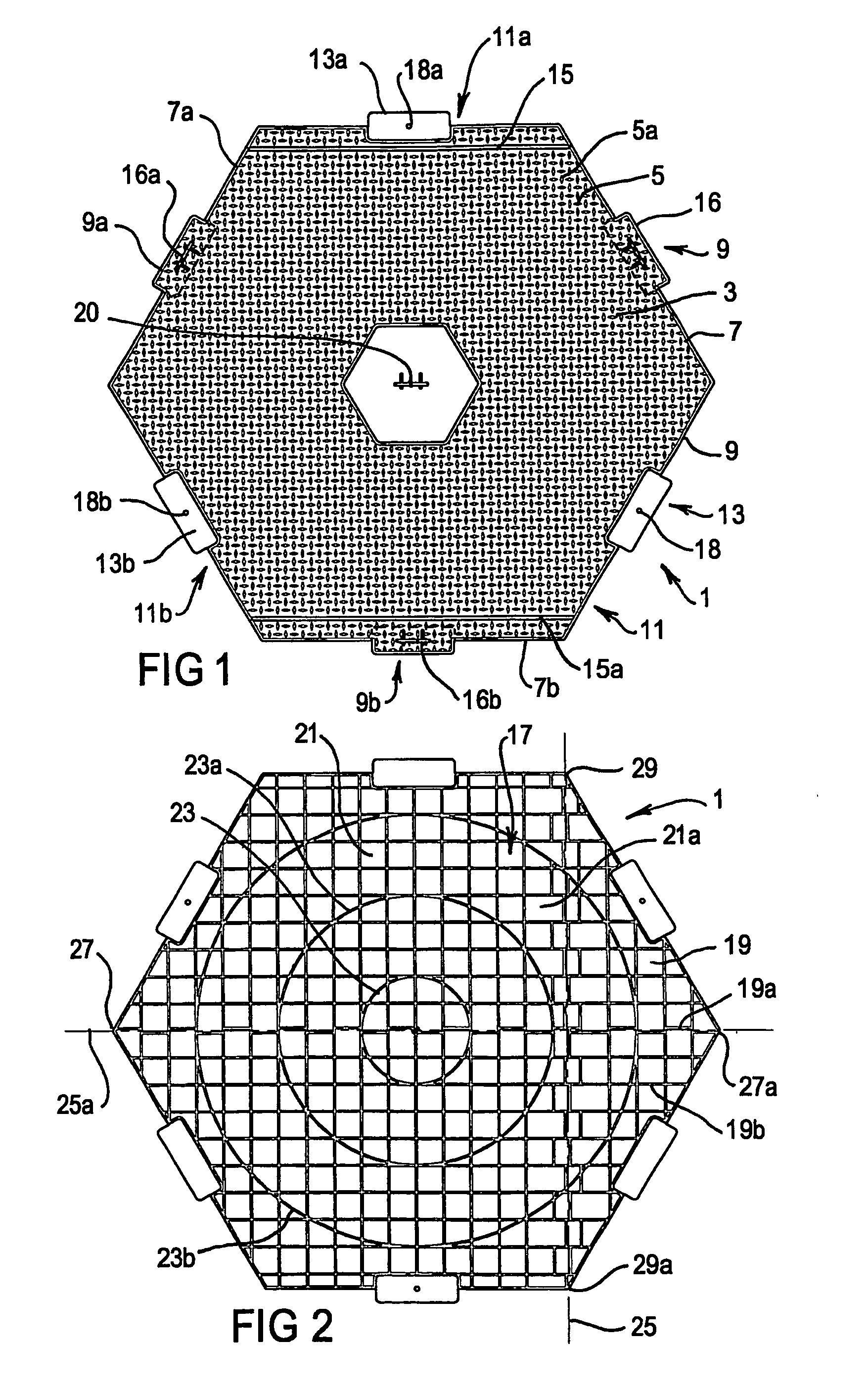
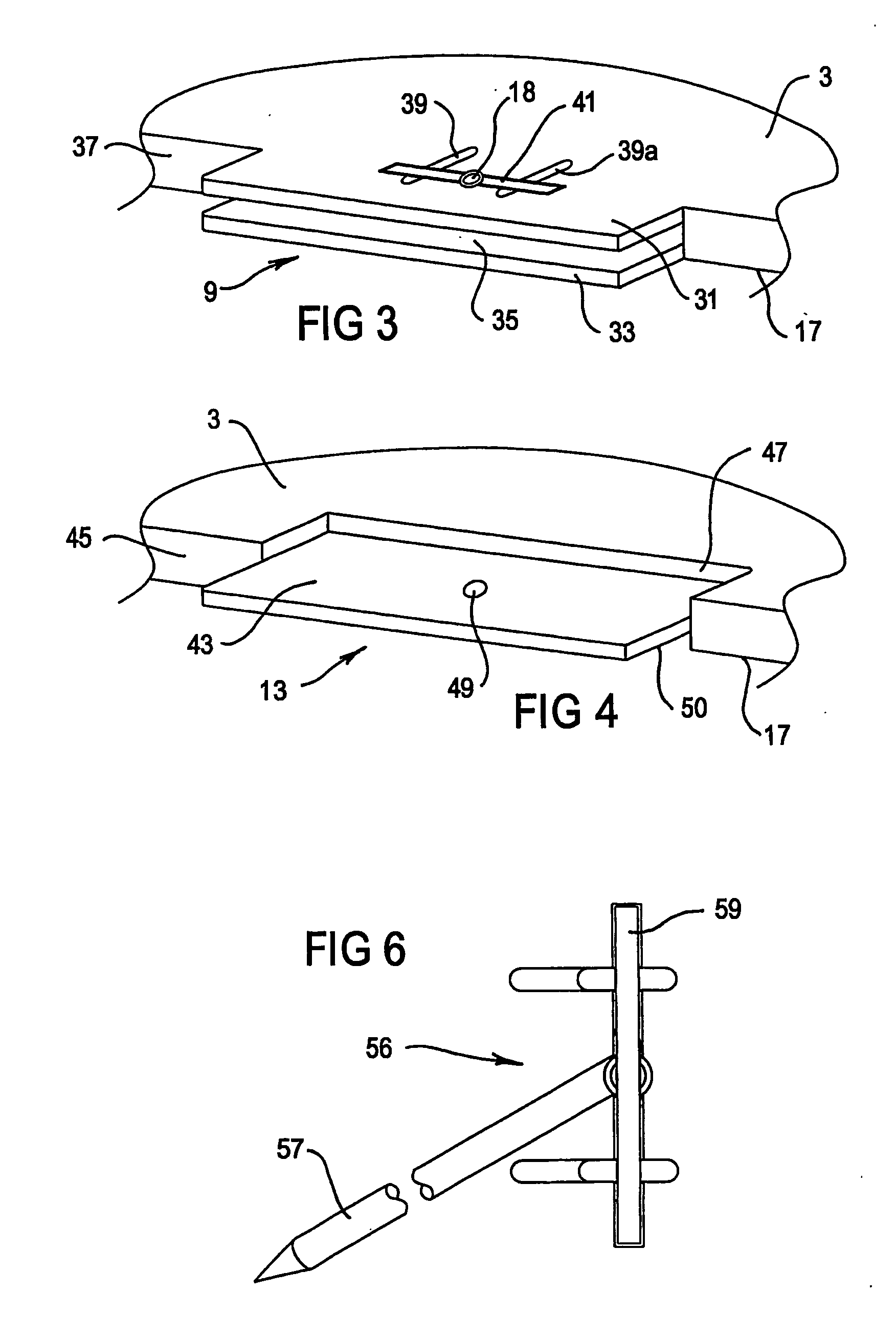
[0025] In FIG. 1, modular decking tile 1 has a planar hexagonal upper surface 3 bearing a pattern of raised friction lugs 5 to provide grip to upper surface 3. Lugs 5 are shown in a chequer plate configuration designed to ensure that wheels of vehicles or footwear of pedestrian traffic does not slip on upper surface 3, particularly when upper surface 3 is wet or muddy. The surface area of upper surface 3 may be up to approximately 3 m2 although smaller or larger versions may be made if desired. Peripheral edges 7, 7a and &7b each have a female connector portion 9, 9a and 9b typically shown in more detail in FIG. 3.

[0026] Peripheral edges 11, 11a and 11b each have male connector portions 13, 13a and 13b typically shown in more detail in FIG. 4.

[0027] Upper surface 3 has recessed lines 15 and 15a which are reduced slightly below the plane of upper surface 3. Recessed lines 15 and 15a may accommodate an adhesive marking tape (not shown) for clearly outlining desired areas of a deckin...


PUM

PropertyMeasurementUnit
Shapeaaaaaaaaaa

Abstract

A tile for forming a modular deck with like-configured tiles, the tile having a web having a planar polygonal upper surface and a lower surface, a web strengthening structure on said lower surface, and a plurality of peripheral edges, where at least one of the edges includes a male connecting portion having a lateral tongue extending from the peripheral edge, and at least one of the edges includes a female connecting portion defining a lateral recess in the peripheral edge. In one embodiment, at least three of the peripheral edges include either of the male connecting portions or the female connecting portions.

Description

RELATED APPLICATIONS [0001] This application is a continuation of PCT / AU2003 / 001010, filed Aug. 8, 2003, which claims priority to AU 2002950813, filed Aug. 9, 2002, the disclosures of which are incorporated by reference herein in their entireties.FIELD OF THE INVENTION [0002] The present invention relates to a modular decking tile, and temporary decking made from modular decking tiles. BACKGROUND OF THE INVENTION [0003] Exploration for mineral resources such as natural gas and oil often takes place in regions remote from civilization. Such exploration sites are often located in remote jungles in tropical climates of high rainfall, in mountainous areas, or in areas of particular environmental sensitivity. When a mining organization selects a site for drilling, one of the initial tasks is to clear a working area of native vegetation, and to construct a working platform on top of the cleared earth on which equipment, buildings and drilling hardware can be assembled. The conventional fo...

Claims


Application Information

Patent Timeline
IPC IPC(8): E01C5/16E01C5/20E01C9/08E04B5/02E04F15/06E04F15/10
CPCE01C5/16E01C5/20E01C9/08E04B5/02E04F2201/096E04F15/06E04F15/10E04F2201/0505E04F2201/091E04B5/026E04F15/02194E04F15/105
Inventor SMART, GREGORY JAMESSMART, LYNDY JANEWOOTTON, DARRYL JOHN
Owner SMART GREGORY JAMES
Learn More