Load-detecting device

a technology of detecting device and supporting member, which is applied in the direction of bumpers, instruments, force/torque/work measurement apparatus, etc., can solve the problems of erroneous actuation of above-described safety mechanism, inability to accurately control the inflation of airbags as described above, and the passenger mortality rate has been declining. , to achieve the effect of increasing the stiffness of the supporting member in the direction other than the detection direction, and reducing the risk of injury

Inactive Publication Date: 2005-09-08
DENSO CORP
View PDF9 Cites 22 Cited by
  • Summary
  • Abstract
  • Description
  • Claims
  • Application Information

AI Technical Summary

Benefits of technology

[0016] In the load-detecting device according to the present invention, the supporting member may have a lower stiffness in the predetermined direction than that in a different direction. It is desirable that the supporting member be elastically deformable in the predetermined direction in which the load is applied (the load detection direction of the load sensor) while having a high stiffness for the other directions (in this case, a radial direction regarding the predetermined direction as a central axial line). The load-detecting device according to the present invention detects a load from the predetermined direction, whereas it does not detect a load from the other directions. Therefore, the stiffness of the supporting member in the directions other than the detection direction is increased so that a load from the directions other than the detection direction is not transferred to the load sensor. As a result, the load-detecting device according to the present invention can detect a load from the predetermined direction with good accuracy. The increased stiffness in the directions other than the predetermined direction can be relatively easily achieved by, for example, increasing a thickness in the directions other than the predetermined direction, changing a material or the like.
[0017] In the load-detecting device of the present invention, the load sensor may be provided in contact with a center of gravity of the elastic displacement area. The position of the center of gravity of the elastic displacement area corresponds to the maximum displacement point of the area. By providing the load sensor in contact with the maximum displacement point, a load is most efficiently transferred from the load transfer member. As a result, the load sensor can detect a load with high accuracy.
[0018] In the load-detecting device according to the present invention, the supporting members may be symmetrically provided about an axial line extending in the predetermined direction from the center of gravity of the elastic displacement area. The position of the center of gravity of the elastic displacement area corresponds to the maximum displacement point in the area, as described above. Therefore, if the supporting members are arranged so as to be symmetrical about the maximum displacement point, the load quotas can be allocated to the respective supporting members in a well-balanced manner, thereby providing stable support for the load transfer member. Specifically, the entire load-detecting device can be constructed to have a high strength against a load from the load detection direction.
[0019] In the load-detecting device according to the present invention, the load sensor may be formed of zirconia and La1−xSrxMnO3 (0≦x≦1) having a pressure resistance effect as chief materials. The load sensor is formed by using zirconia particles as a matrix material and having La1−xSrxMnO3 particles, which serve as a pressure resistance material, dispersed therein so as to be electrically continuous. As a result, an ohmic resistance is varied based on the application of a load to enable the load detection based on the variation in ohmic resistance. Since zirconia has an excellent heat resistance and, therefore, hardly induces a variation in temperature in the sensor, a detection error due to a variation in temperature in the sensor is hardly generated. Moreover, since zirconia has toughness, a sensor structure having an extremely high resistance against breakage due to a load or a pressure can be obtained. Furthermore, in the present invention, an increased strength of the load sensor also contributes to the increase in stiffness of the entire load-detecting device according to the present invention. Although the load transfer member is required to have a lower stiffness than that of the load sensor in the present invention, the members other than the load transfer member can have a higher stiffness than that of the load sensor. Therefore, the increased strength of the load-detecting device also contributes to the increase in stiffness of the load transfer member. As a result, the stiffness of the entire load-detecting device can be increased. Such a load-detecting device may be provided in various mechanisms as a structure.
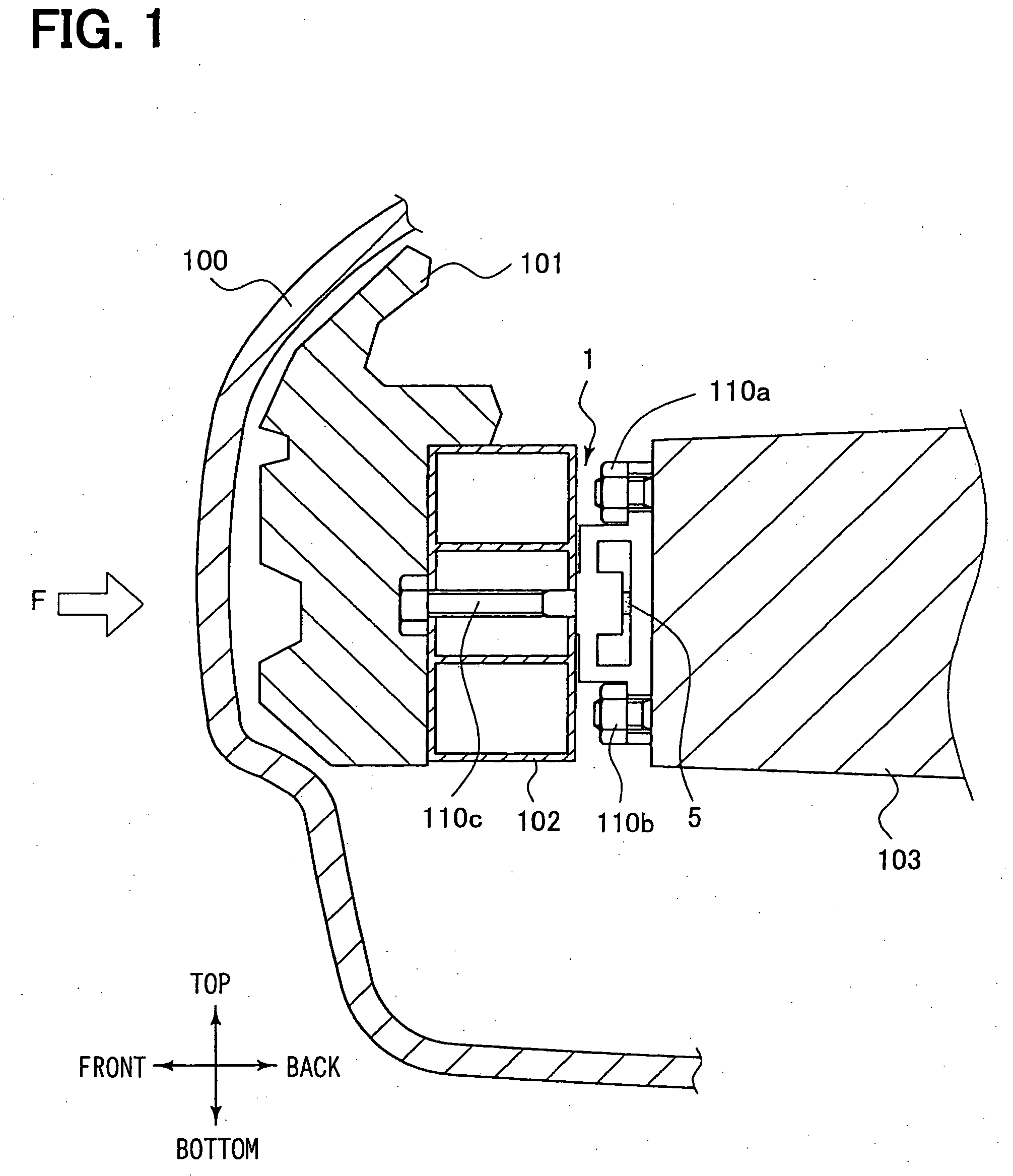
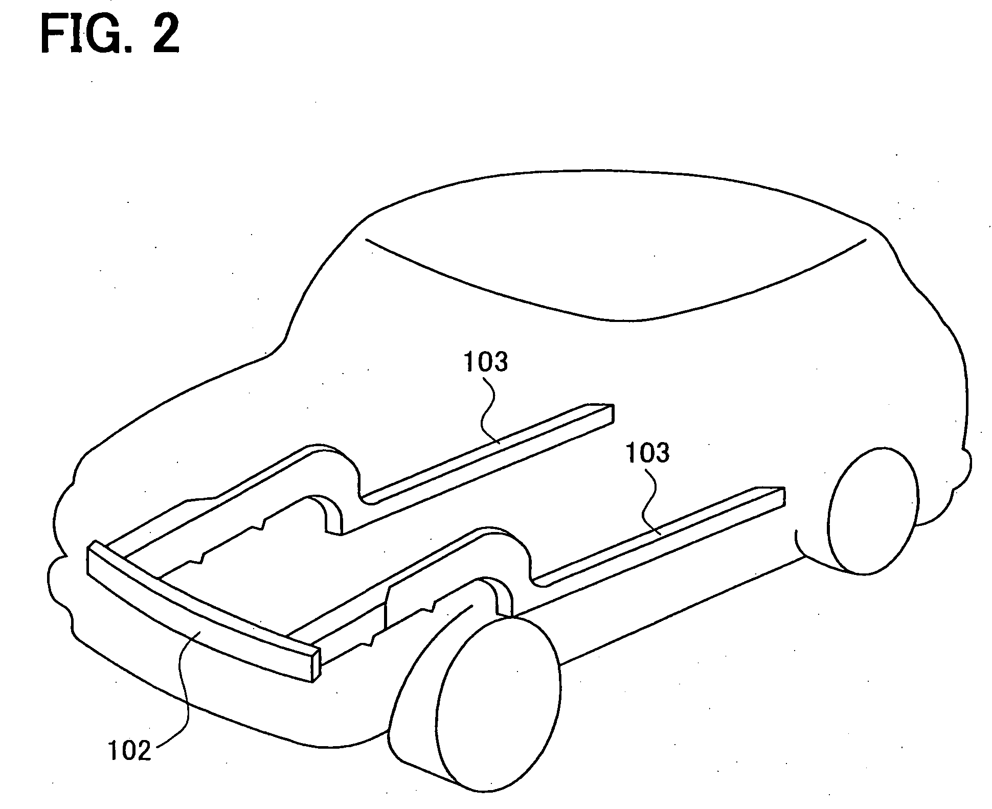
[0020] Moreover, the load-detecting device according to the present invention may be interposed between a bumper reinforcement extending in a horizontal direction of the vehicle (the bumper reinforcement is connected to an energy absorber provided under a bumper cover of the vehicle) and the vehicle front sides of side members extending in a longitudinal direction of the vehicle so as to detect a load applied from the vehicle bumper side. If an impact on the bumper from a traveling direction of the vehicle (the front of the vehicle) is to be detected as a load, the detection of a load from the directions other than the vehicle traveling direction leads to an error for detection of the impact with high accuracy. Therefore, the load-detecting device according to the present invention, which is capable of detecting a load from a predetermined direction with good accuracy, is suitable for the detection of an impact load on the bumper. Moreover, since the load-detecting device of the present invention can be constructed to have a high stiffness as a whole, as described above, the load detection can withstand a large impact load on the bumper.
[0021] Furthermore, the load-detecting device according to the present invention may be provided between a seating face of a vehicle seat and a floor constituting a part of a vehicle body so as to detect a load applied to the seating face of the vehicle seat. In the case where a weight applied to the vehicle passenger seat is to be detected, the detection of a load from a longitudinal or horizontal direction of the vehicle produces an error in detection of the weight applied to the passenger seat with high accuracy. Therefore, the load-detecting device of the present invention, which is capable of detecting a load from the predetermined direction with good accuracy, is suitable for detecting the weight on the passenger seat for passenger detection.

Problems solved by technology

As a result, a passenger mortality rate has been declining in recent years.
Therefore, the control of inflation of the air bag as described above and the like cannot be accurately performed.
As a result, there is a possibility the above-described safety mechanism may be erroneously actuated to open a hood, to inflate an air bag on the hood, or perform some other safety measure.
Since the detection sensitivity greatly varies depending on a stiffness ratio of the flat spring to the detecting unit, a length of the flat spring and the like, the components and the assembly of the components require high accuracy, resulting in high cost.
Moreover, there is another problem that, for example, a large detection dynamic range cannot be ensured for the strength in the case where a tensile load is applied in the same direction as a load detection direction.
Moreover, since the area required to place the load sensor is large, the cost is disadvantageously elevated.
However, the bumper R / F supports a member for absorbing an impact on the front side of a vehicle and, therefore, must have a high stiffness and a large mass.
As a result, an impact load cannot be detected with high accuracy.

Method used


Image

  • Load-detecting device
  • Load-detecting device
  • Load-detecting device

Examples


second embodiment

[0055]FIG. 5 shows the present invention, illustrating a simplified structure of a passenger seat 200 of a vehicle equipped with the load-detecting device 1. The passenger seat 200 includes a bottom frame section 201 for forming a seating face, a back frame section 202 for a back rest face, and a connecting section 204 for pivotally supporting the back frame section 202 to the bottom frame section 201. The passenger seat 200 is composed of a seat cushion 210a on the seating face and a seat back 210b serving as a back rest. An arm 205 is fixedly provided on a floor 300 of the vehicle. The load-detecting device 1 according to the present invention is provided between the arm 205 and the bottom frame section 201 so as to be able to detect a load applied to the seat, that is, the weight of a passenger.

first embodiment

[0056]FIG. 6 is an enlarged view of the load-detecting device shown in FIG. 5. The load-detecting device 1 includes the load transfer member 2, the supporting members 3, the load sensor supporting member 4, and the load detection sensor 5 as the load-detecting device shown in FIG. 3. In the load-detecting device shown in FIG. 5, however, the load transfer member 2 and the supporting members 3 form an integral structure, and the supporting members 3 are fitted and fixed by upwardly projecting portions provided on the both ends of the load sensor supporting member 4. A fastening member 110d serves to be fastened to the frame section 201 forming the seating face, whereas a fastening member 110e serves to be fastened to the arm 205 fixedly provided on the floor 300 of the vehicle. Each of the fastening members 110d and 110e is composed of a bolt and a nut in this embodiment. Since the principle of load detection is the same as that of the first embodiment described above, the detailed d...


PUM

PropertyMeasurementUnit
forceaaaaaaaaaa
elastic displacementaaaaaaaaaa
stiffnessaaaaaaaaaa

Abstract

A load-detecting device includes a supporting member, a load transfer member, a load sensor, and a load sensor supporting member. The load transfer member is supported by the supporting member and includes an elastic displacement area in which an elastic displacement is generated upon receiving a force from a predetermined direction. The load sensor contacts the elastic displacement area of the load transfer member. The load sensor detects a load based on the elastic displacement. The load sensor supporting member supports the load sensor and is connected to the supporting member. The load transfer member, the load sensor, and the load sensor supporting member are provided in this order along the predetermined direction. The supporting member is provided so as not to be in contact with the load sensor. The load transfer member has a lower stiffness in the predetermined direction than the load sensor.

Description

CROSS REFERENCE TO RELATED APPLICATIONS [0001] This application is based upon and claims the benefit of priority of Japanese Patent Application No. 2004-60774, filed on Mar. 4, 2004, the contents of which are incorporated herein by reference. FIELD OF THE INVENTION [0002] The present invention relates to a load-detecting device and, more particularly, to a load-detecting device for detecting an impact to a vehicle that is applied in a predetermined direction. BACKGROUND OF THE INVENTION [0003] As can be seen from an automobile equipped with a seat belt and / or an air bag for ensuring the safety of a passenger, the importance of safety has been recently recognized and safety measures have been taken. As a result, a passenger mortality rate has been declining in recent years. On the other hand, although the development of safety measures for pedestrians is relatively slower than various measures for protecting passengers, its technical development is in progress. [0004] The air bag for...

Claims


Application Information

Patent Timeline
Patent Type & Authority Applications(United States)
IPC IPC(8): G01G19/12B60N2/90B60R19/24B60R21/00B60R21/16G01G19/52G01L1/00G01L1/26
CPCB60N2/002B60R19/18B60R19/24G01L5/0052B60R2019/182B60R2019/1873G01G19/4142B60R19/48
Inventor MORIKAWA, KENJI
Owner DENSO CORP
Why Eureka
Try Eureka