Focused parametric array

a parametric array and focused technology, applied in the field of parametric sound reproduction, can solve the problems of not being able to focus sound in a practical manner, parametric loudspeakers have had difficulty in creating focused, wideband audio signals, and not being able to achieve parametric sound the effect of focusing sound wideband

Inactive Publication Date: 2005-09-08
AMERICAN TECH
View PDF99 Cites 45 Cited by
  • Summary
  • Abstract
  • Description
  • Claims
  • Application Information

AI Technical Summary

Benefits of technology

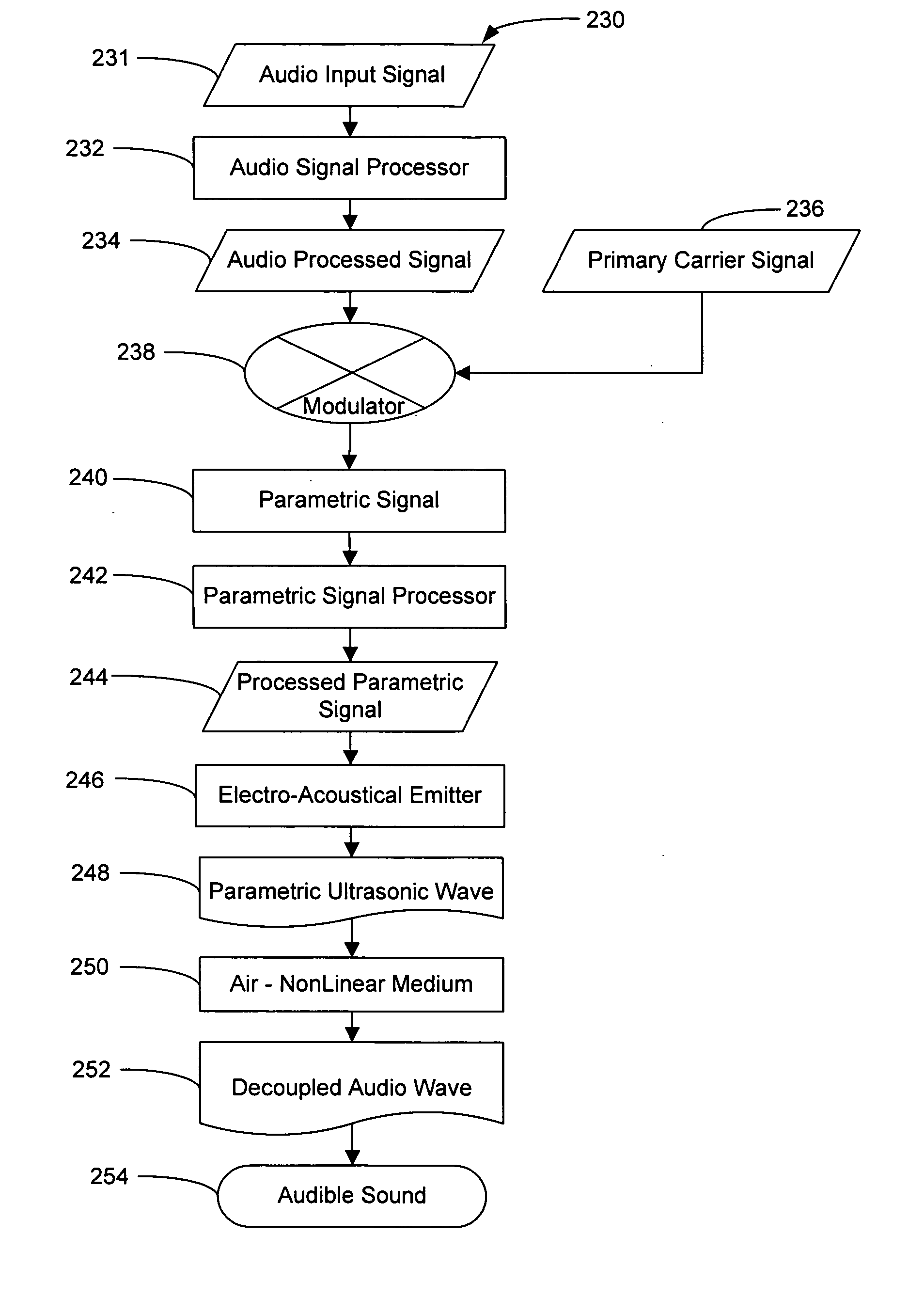
[0008] A parametric sound system for creating an acoustical column along an axis of propagation having a quiet zone an audible zone is disclosed. The system comprises a parametric electro-acoustic emitter configured for emitting a plurality of focalized parametric ultrasonic waves. A plurality of decoupled acoustic waves are maximized at a focalizing area within the audible zone. The system also includes a signal source for applying a parametric ultrasonic signal to the parametric electroacoustic emitter. The signal includes an ultrasonic carrier signa...

Problems solved by technology

Despite developments in directional sound, it has not been feasible with either parametric or conventional sound to focus wideband audio signals to a specific location.
Conventional loudspeakers have not been able to focus sound in a practical manner because in order to create focused sound propagation, devices of large sizes relative to audio wavelengths are required.
Likewise, parametric loudspeakers have had difficulty in creating focused, wideband audio signals.
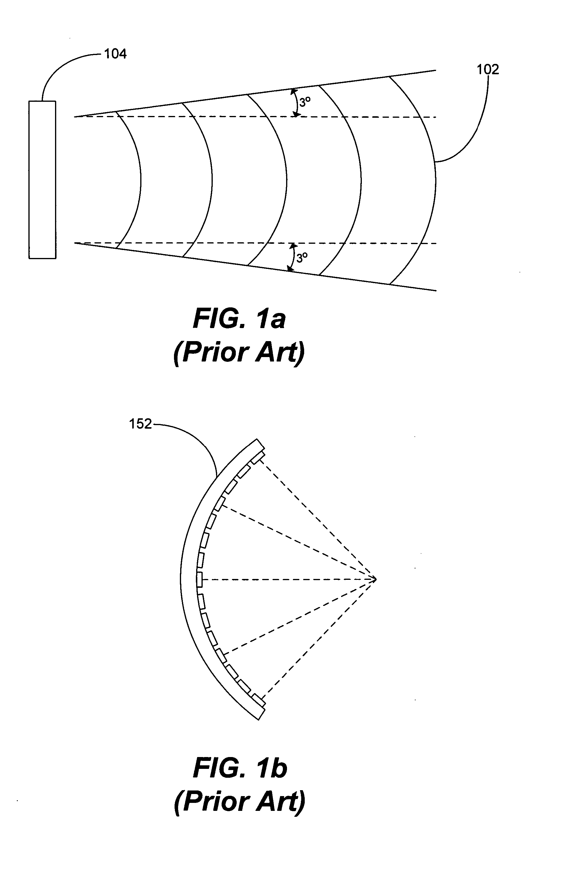
In addition to the unwanted dispersion of 3°, typical parametric loudspeakers often produce sidelobes which can be de...

Method used


Image

  • Focused parametric array
  • Focused parametric array
  • Focused parametric array

Examples


Embodiment Construction

[0043] Reference will now be made to the exemplary embodiments illustrated in the drawings, and specific language will be used herein to describe the same. It will nevertheless be understood that no limitation of the scope of the invention is thereby intended. Alterations and further modifications of the inventive features illustrated herein, and additional applications of the principles of the inventions as illustrated herein, which would occur to one skilled in the relevant art and having possession of this disclosure, are to be considered within the scope of the invention.

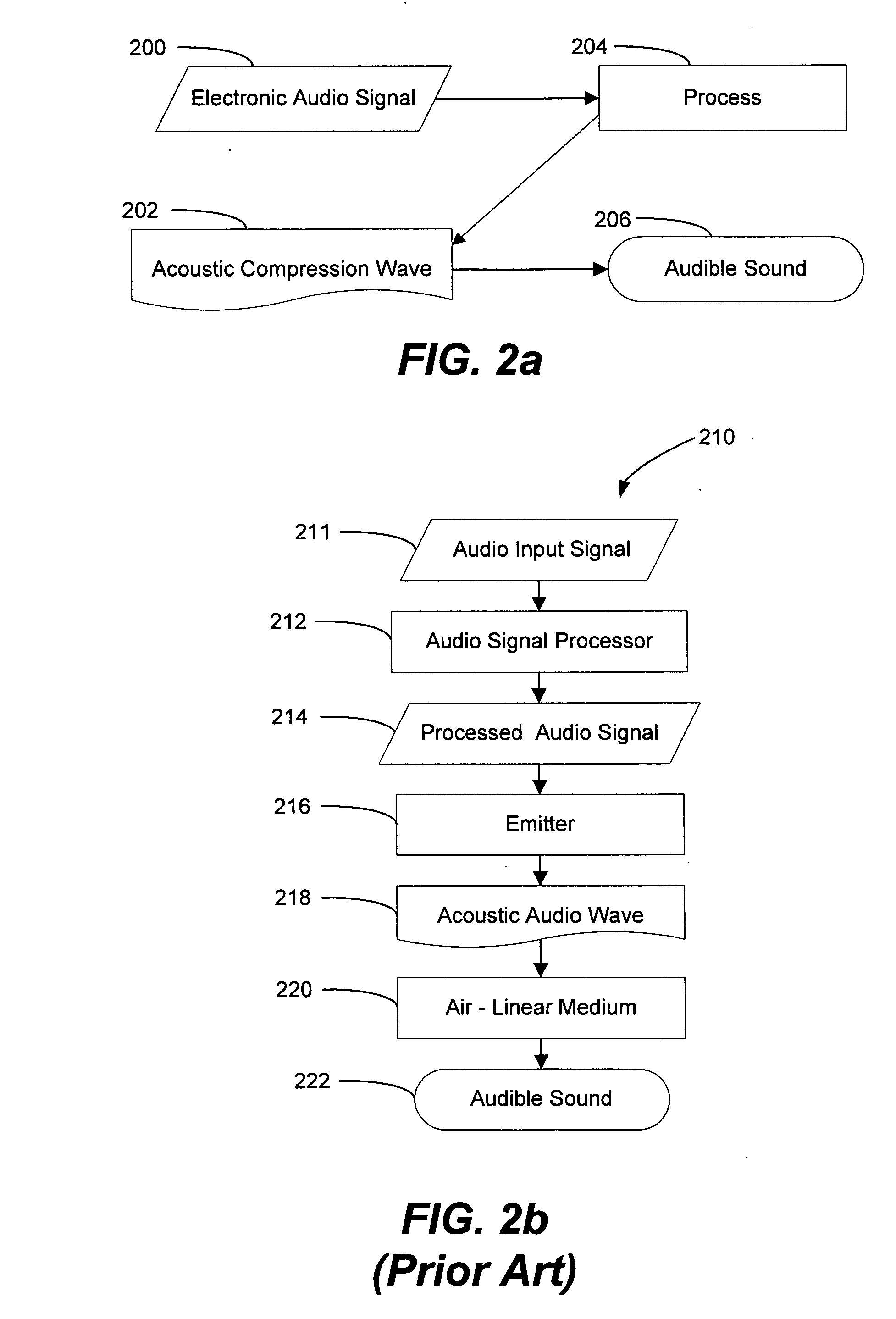
[0044] Because parametric sound is a developing field, and in order to identify the distinctions between parametric sound and conventional audio systems, the following definitions, along with explanatory diagrams, are provided. While the following definitions may also be employed in future applications from the present inventor(s), the definitions are not meant to retroactively narrow or define past application...


PUM


Abstract

A parametric sound system for creating an acoustical column along an axis of propagation having a quiet zone an audible zone is disclosed. The system comprises a parametric electro-acoustic emitter configured for emitting a plurality of focalized parametric ultrasonic waves. A plurality of decoupled acoustic waves are maximized at a focalizing area within the audible zone. The system also includes a signal source for applying a parametric ultrasonic signal to the parametric electroacoustic emitter. The signal includes an ultrasonic carrier signal and one or more sideband signals corresponding to an audio input signal. The system further comprises a signal processor for controlling phases of the parametric ultrasonic signal so that the plurality of focalized parametric ultrasonic waves emitted by the parametric electro-acoustic emitter will create a quiet zone along the same direction of propagation as the audible zone. The plurality of decoupled audio waves are substantially in phase within the audible zone while the plurality of decoupled audio waves are largely out-of-phase within the quiet zone.

Description

[0001] This application is a continuation-in-part of U.S. patent application Ser. No. 09 / 430,801 filed Oct. 29, 1999 and claims priority to U.S. Provisional Patent Application Ser. No. 60 / 547,487 filed Feb. 25, 2004, each of which are incorporated herein by reference. This application also claims priority to U.S. patent application Ser. No. 09 / 850,523 filed May 7, 2001, Ser. No. 10 / 458,498 filed Jun. 9, 2003, Ser. No. 10 / 101,426 filed Mar. 18, 2002, U.S. Provisional Patent Application Ser. No. 60 / 496,834 filed Aug. 21, 2003, and International Patent Application Serial No. PCT / US / 00 / 00 103 filed Jan. 4, 2000, each of which are incorporated herein by reference.BACKGROUND OF THE INVENTION [0002] 1. Field of the Invention [0003] The present invention relates generally to audio reproduction. More specifically, this invention relates to parametric sound reproduction. [0004] 2. Related Art [0005] One of the most unusual distinctions between parametric and conventional sound relates to dire...

Claims


Application Information

Patent Timeline
IPC IPC(8): H04R17/00
CPCH04R2217/03H04R17/00
Inventor CROFT, JAMES J. IIILIU, WENSEN
Owner AMERICAN TECH
Why Eureka
Try Eureka