Closed circuit energy recovery system for a work implement

a closed circuit energy recovery and work implement technology, applied in the direction of fluid couplings, piston pumps, servomotors, etc., can solve the problems of ineffective use of systems in work vehicles, insufficient risk of damage or malfunction due to cavitation, and insufficient risk of damage or malfunction, so as to reduce the risk of cavitation and reduce the loss of post compensation.

Active Publication Date: 2005-09-08
DEERE & CO
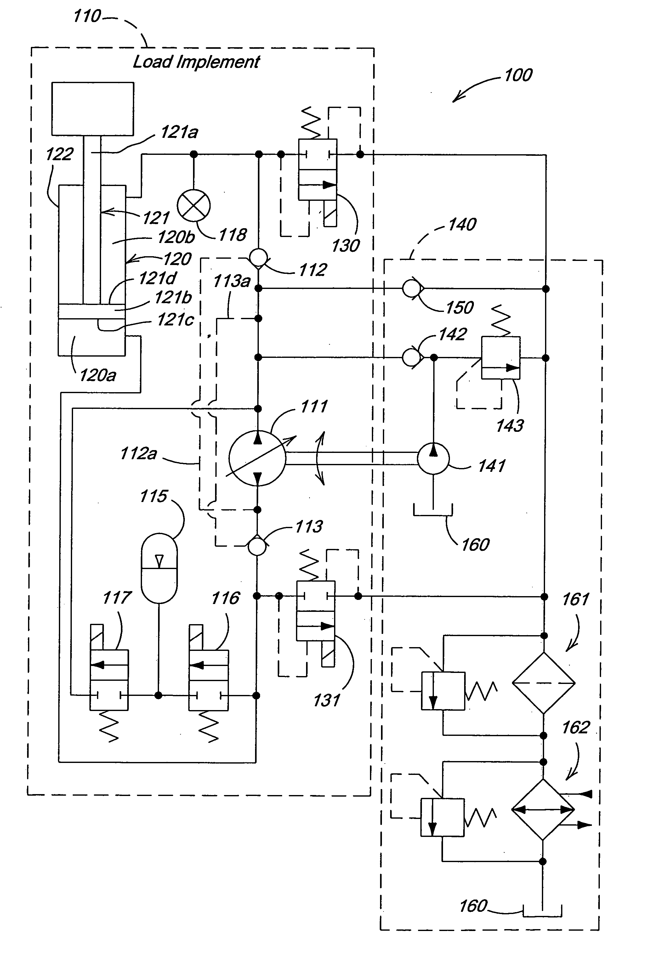
View PDF10 Cites 40 Cited by
  • Summary
  • Abstract
  • Description
  • Claims
  • Application Information

AI Technical Summary

Benefits of technology

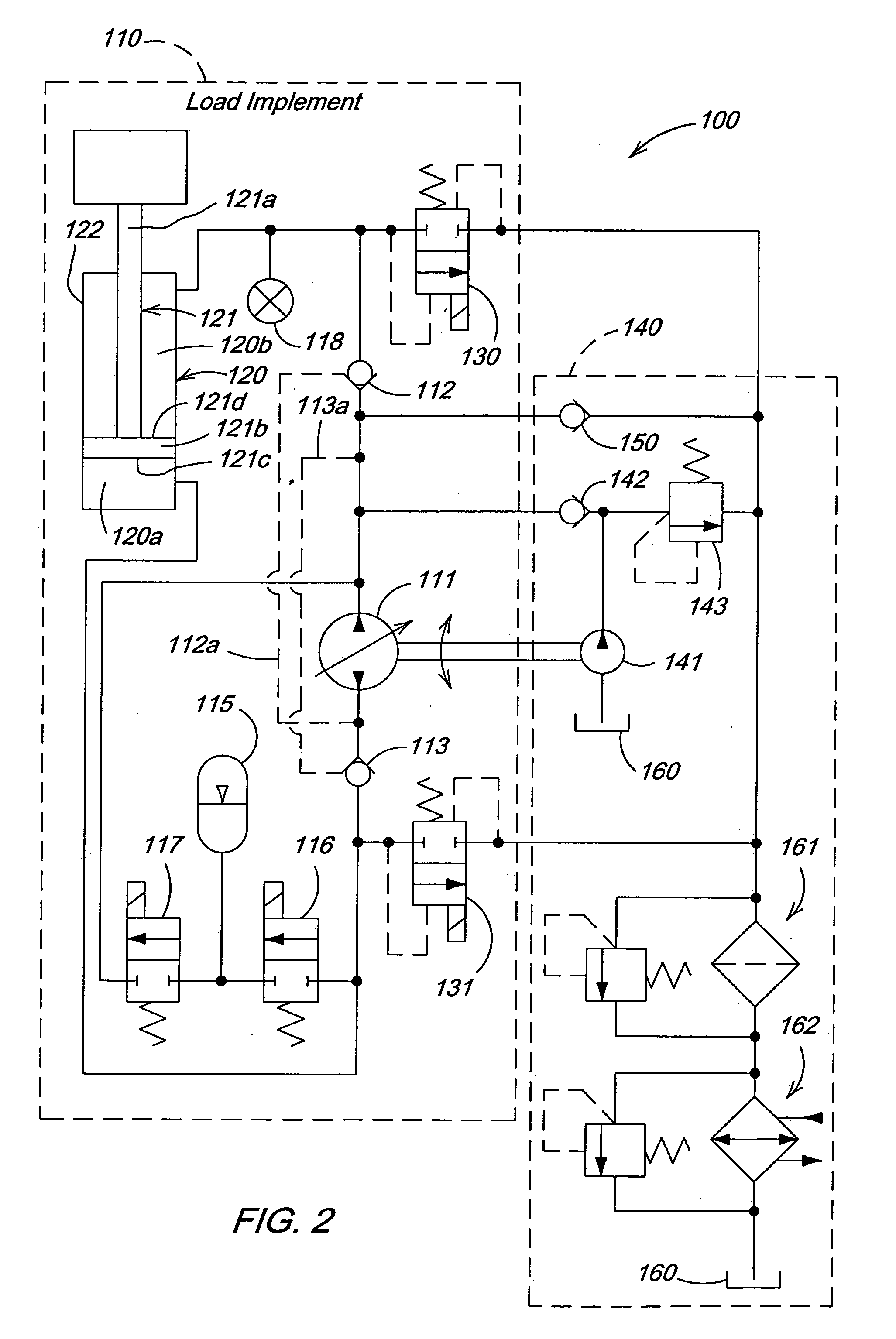
[0004] As stated earlier, in conventional work vehicles, displacement control valves are used to direct flow from the hydraulic pumps for retraction or extension of the cylinder. However, this results in inefficiencies in the system as there are hydraulic pressure losses across the displacement control valves. In some technical literature, variable displacement hydraulic pumps are used to determine the direction of flow, thus, eliminating the need for displacement control valves for this function. However, such systems have not, heretofore, been actually utilized in a work vehicle to, for example, manipulate a work tool to do useful work. Provided herein is a closed circuit hydraulic system for a work vehicle that eliminates the displacement control valve through the use of an electro-hydraulic variable displacement hydraulic pump. The displacement pump controls the rate of fluid flow via adjustments in its displacement volume. It also determines the direction in which fluid flows for work purposes as it is multi-directional. Thus, a system is presented and claimed in which losses due to post compensation are substantially reduced in comparison to conventional systems.
[0005] As stated earlier, in conventional systems the risk of damage or malfunction due to cavitation is substantially reduced through the use of complex and expensive valves. Provided herein is an apparatus and a method to substantially reduce the risk of cavitation through the use of an accumulator and an inexpensive check valve with a low pressure drop for fluid make up.
[0006] In conventional systems the float function, i.e., the ability of the work tool to rest on and follow the contours of the earth as the work vehicle moves along the ground, is accomplished via a function in the displacement control valve. However, in the closed circuit provided herein the displacement control valve is eliminated along with the inefficiencies associated with nominal losses as the fluid passes through the valve. Provided herein is an apparatus and a method of accomplishing the float function without a displacement valve.

Problems solved by technology

However, this results in inefficiencies in the system as there are hydraulic pressure losses across the displacement control valves.
However, such systems have not, heretofore, been actually utilized in a work vehicle to, for example, manipulate a work tool to do useful work.
As stated earlier, in conventional systems the risk of damage or malfunction due to cavitation is substantially reduced through the use of complex and expensive valves.

Method used


Image

  • Closed circuit energy recovery system for a work implement
  • Closed circuit energy recovery system for a work implement
  • Closed circuit energy recovery system for a work implement

Examples


Embodiment Construction

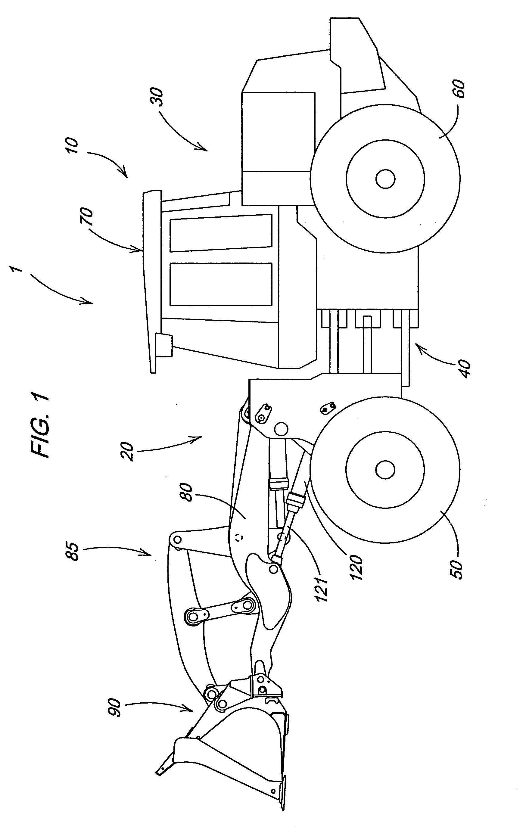
[0010]FIG. 1 illustrates a work vehicle in which the invention may be used. The particular work vehicle illustrated in FIG. 1 is an articulated four wheel drive loader 1 having a main vehicle body 10 that includes a front vehicle portion 20 pivotally connected to a rear vehicle portion 30 by vertical pivots 40, the loader being steered by pivoting of the front vehicle portion 20 relative to the rear vehicle portion 30 in a manner well known in the art. The front and rear vehicle portions 20 and 30 are respectively supported on front drive wheels 50 and rear drive wheels 60. An operator's station 70 is provided on the rear vehicle portion 30 and is generally located above the vertical pivots 40. The front vehicle portion 20 includes a boom 80, a linkage assembly 85, a work tool 90 and a hydraulic cylinder 120. The front and rear drive wheels 50 and 60 propel the vehicle along the ground and are powered in a manner well known in the art.

[0011]FIG. 2 illustrates a hydraulic circuit 10...


PUM


Abstract

A closed circuit hydraulic system includes a fluid reservoir, a hydraulic cylinder having a cylinder rod, a bidirectional variable displacement hydraulic pump that pumps fluid to either extend or retract the cylinder rod on demand, a flow control valve for relieving pressure between the variable displacement hydraulic pump and the cylinder, and a low pressure check valve between the variable displacement hydraulic pump and the fluid reservoir. Also included is a charge pump for charging the variable displacement hydraulic pump and an accumulator for saving extra energy and fluid from the hydraulic cylinder during the retraction of an extended cylinder rod and using that fluid and energy during the extension of the hydraulic cylinder to reduce a load on the charge pump. The flow control valve opens on demand to allow floating. The low pressure check valve opens when pressure at an inlet of the variable displacement hydraulic pump is low to provide additional fluid and pressure so as to avoid cavitation. A method for using the closed circuit hydraulic system is also provided.

Description

FIELD OF THE INVENTION [0001] The invention relates to an energy recovery circuit for a hydraulic apparatus of a work vehicle such as a loader, a backhoe or the like. BACKGROUND OF THE INVENTION [0002] In modern work vehicles, hydraulic circuits are used to power the hydraulic cylinders that manipulate work implements. Such systems may use pumps of the variable displacement type which control the flow rate of hydraulic fluid via manipulation of their displacement volumes. A displacement control valve is used to determine the direction of fluid flow to accomplish the work desired, i.e., for example, to extend or retract the hydraulic cylinder. The displacement control valve is also used to allow free flow of fluid so as to minimize pressure generated, i.e., to enable floating; an operating mode in which an implement rests on and follows the contours of the earth as the work vehicle is propelled along the ground. [0003] In an overwhelming majority of hydraulic systems for work vehicle...

Claims


Application Information

Patent Timeline
Patent Type & Authority Applications(United States)
IPC IPC(8): B66F9/22E02F9/20F04B17/00E02F9/22F04B23/08F04B35/00F15B11/02F15B11/08F15B11/12F15B11/17F15B21/14
CPCE02F9/2217
Inventor CHERNEY, MARK JOHN
Owner DEERE & CO
Why Eureka
Try Eureka