Optical arrangement and a microscope

Inactive Publication Date: 2009-03-05
LEICA MICROSYSTEMS CMS GMBH
View PDF13 Cites 2 Cited by
  • Summary
  • Abstract
  • Description
  • Claims
  • Application Information

AI Technical Summary

Benefits of technology

[0005]Accordingly, the task of the present invention is to provide an optical arrangement and a microscope of the aforementioned type, which enables the compensation or reduction of a curvature of field in an intermediate image with simple structural means.
[0008]Consequently, the optical arrangement according to the present invention provides an optical arrangement which enables the compensation or reduction of a field curvature with simple structural means.
[0016]In accordance with the imaging of the intermediate image in the plane on a zone-by-zone or point-by-point basis, the detector may dispose a CCD array, a CMOS or an APD chip. Said detector further enables a detection and analysis of the image on a zone-by-zone or point-by-point basis.
[0023]Using the optical arrangement according to the invention and the microscope according to the invention it is possible to reduce the curvature of an intermediate image or the field curvature of an optical system to a plane. To achieve this, a specially structured optical medium—the optical element - is used. For example, the optical element may exhibit micro-capillary structures. They may be made up of capillaries arranged next to each other, acting pointwise as optical waveguides and enable a point-to-point imaging from one end of the optical element to the other end. By arranging the optical element in an imaging beam bath it is possible to compensate field errors. The optical waveguides can be arranged array-like so that the transmitted light only emerges at certain points arranged in an array-like manner. The points may be arranged such that they just concur with the sensitive areas of a detector array.

Problems solved by technology

Depending on the optical assembly used, the known optical arrangements are very prone to field curvatures in the intermediate image.
However, said lens systems are complex in their structure and complicated to operate.

Method used


Image

  • Optical arrangement and a microscope
  • Optical arrangement and a microscope
  • Optical arrangement and a microscope

Examples


Embodiment Construction

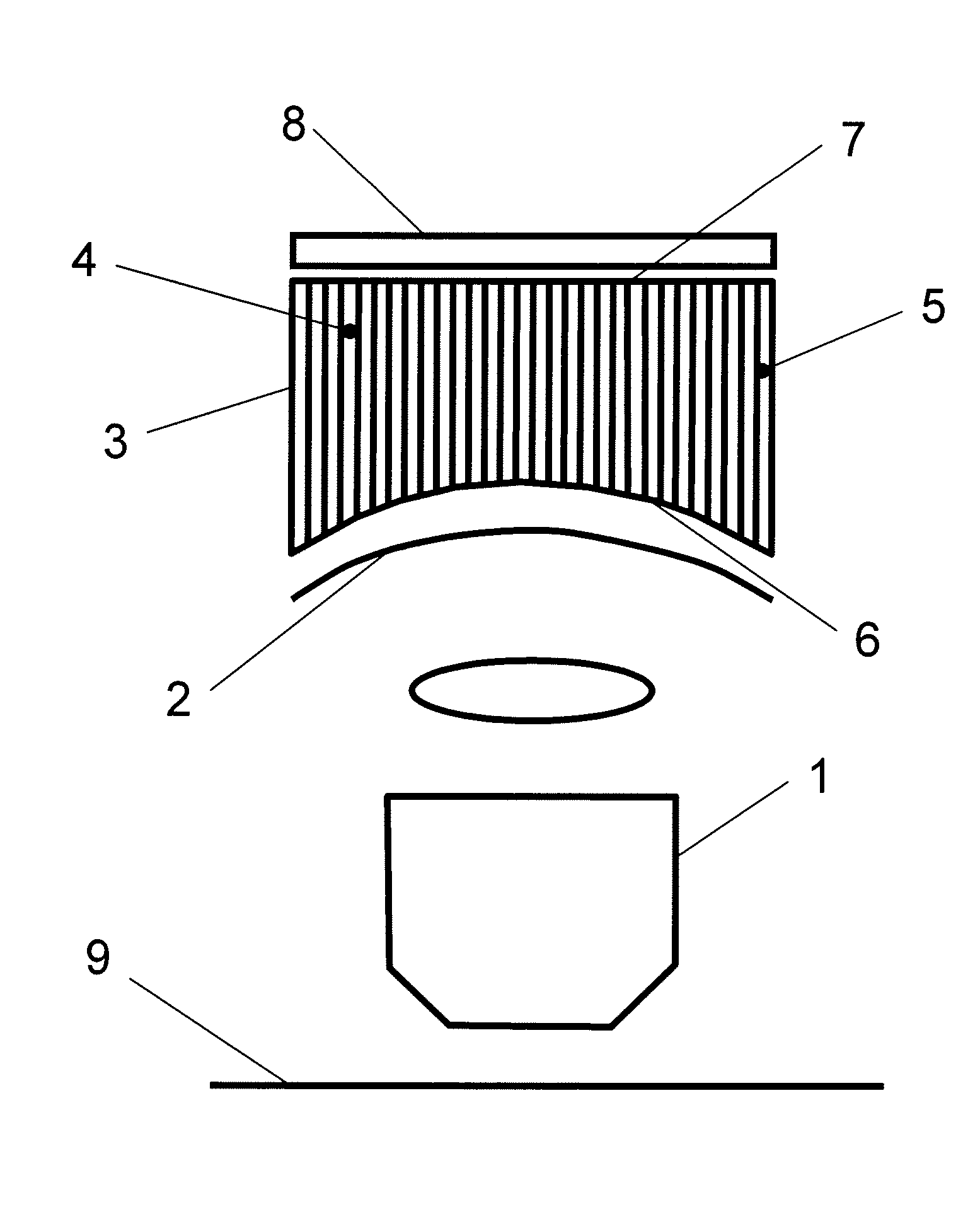
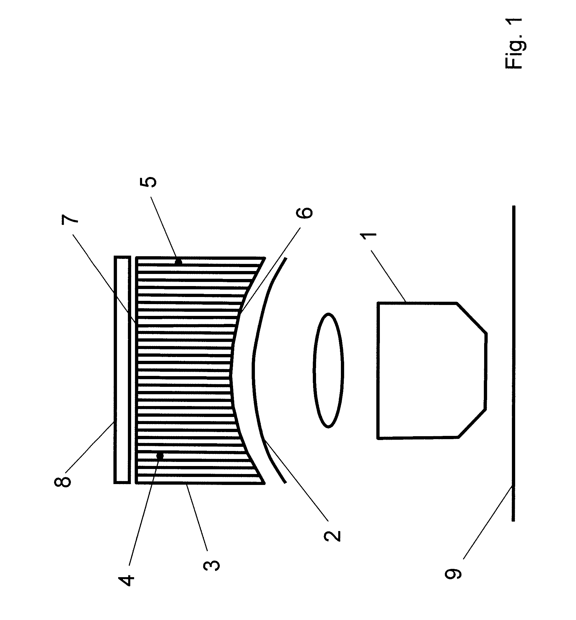
[0029]FIG. 1 shows an embodiment of an optical arrangement according to the invention having an optical component 1 for generating an intermediate image 2 in a beam path. With regard to a compensation or reduction of a field curvature with the aid of simple structural means, an optical element 3 having a plurality of optical waveguides 4 is arranged in the beam path after the intermediate image 2 to enable the imaging of the intermediate image 2 in a plane on a zone-by-zone or point-by-point basis.

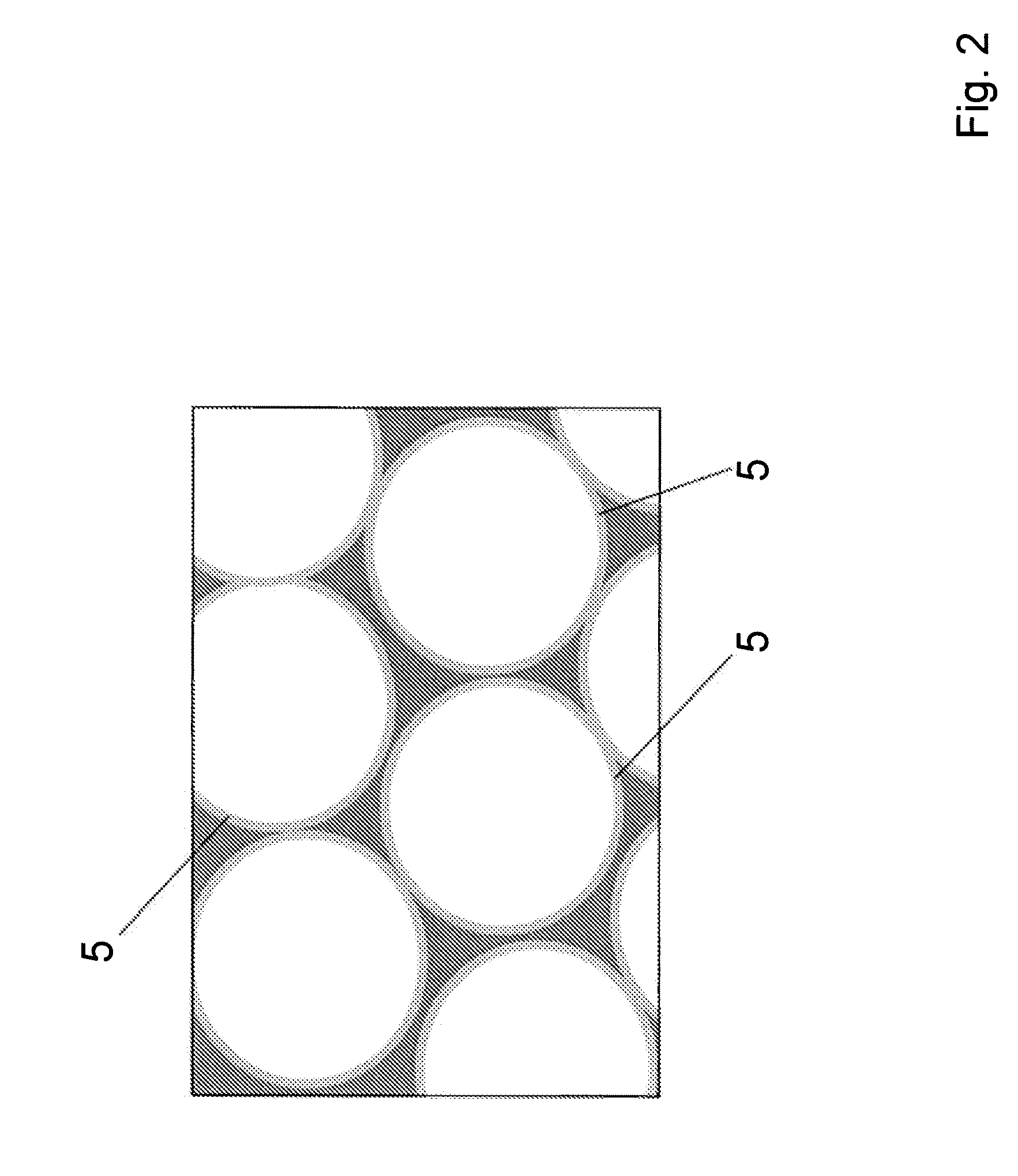
[0030]The optical waveguides 4 are arranged in parallel and next to each other and are formed as capillaries 5 or preferably as micro-capillaries. As a result, the intermediate image 2 is imaged in a plane on a quasi point-by-point or zone-by-zone basis. A curvature of the intermediate image 2 is thereby compensated.

[0031]The input end 6 of the optical element 3 is adapted to the curvature of the intermediate image 2. The output end 7 of the optical element 3 has a planar form.

[0032]At the...


PUM


Abstract

An optical arrangement having an optical assembly (1) for generating an intermediate image (2) in a beam path is configured and further developed such that an optical element (3) having a plurality of optical waveguides (4) is arranged in the beam bath after the intermediate image (2) to enable the imaging of the intermediate image (2) in a plane on a zone-by-zone or point-by-point basis. Further, a microscope exhibiting such an optical arrangement is specified.

Description

CROSS-REFERENCE TO RELATED PATENT APPLICATIONS[0001]The right of foreign priority is claimed under 35 U.S.C. § 119(a) based on Federal Republic of Germany Application No. 10 2007 039 988.1, filed Aug. 23, 2007, the entire contents of which, including the specification, drawings, claims and abstract, are incorporated herein by reference.BACKGROUND OF THE INVENTION[0002]The present invention relates to an optical arrangement with an optical assembly for the generation of an intermediate image in a beam path. The present invention further relates to a microscope containing said optical arrangement.[0003]Optical arrangements and microscopes of the aforementioned type are known in the field and exist in the most varying embodiments. Depending on the optical assembly used, the known optical arrangements are very prone to field curvatures in the intermediate image. Such field curvatures occur, for example, when employing chromatically optimized lens systems (TOH). Indeed this means that a ...

Claims


Application Information

Patent Timeline
IPC IPC(8): G02B21/36G02B21/00
CPCG02B21/361G02B6/06
Inventor STORZ, RAFAELSEYFRIED, VOLKER
Owner LEICA MICROSYSTEMS CMS GMBH
Why Eureka
Try Eureka