Method and apparatus for activating water

Inactive Publication Date: 2005-09-08
MOCHIZAI TADASHI
View PDF2 Cites 6 Cited by
  • Summary
  • Abstract
  • Description
  • Claims
  • Application Information

AI Technical Summary

Benefits of technology

[0018] With this, it is possible to achieve a water activating apparat

Problems solved by technology

Other than intensifying the magnetic force, there is no way to improve the efficiency of water activation.
Therefore, the degree of activation is disadvantageously low and insufficient.
This apparatus has a structural problem, however, that a carbon electrode has to be fitted into the water flow tube, thereby disadvantageously causing an inconvenience of adherence for the purpose of preventing water leak

Method used


Image

  • Method and apparatus for activating water
  • Method and apparatus for activating water
  • Method and apparatus for activating water

Examples


Example

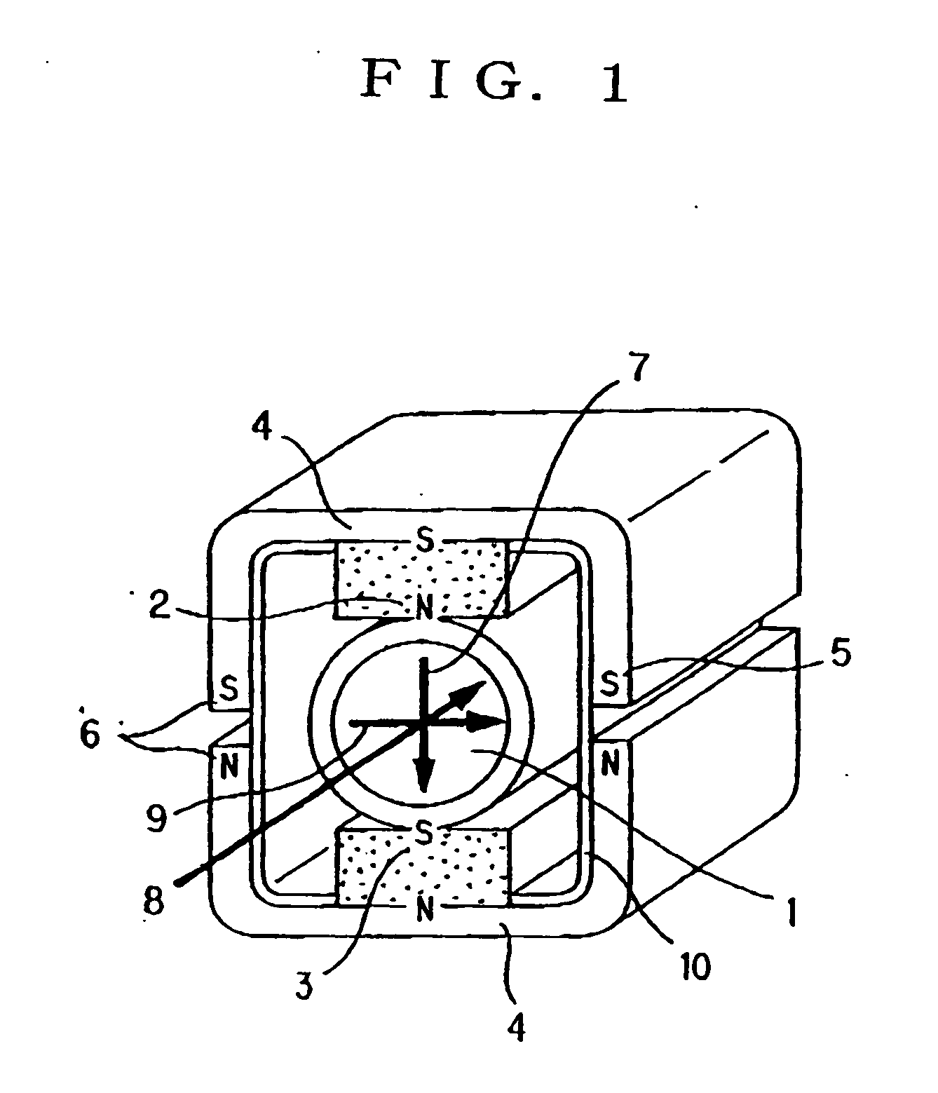
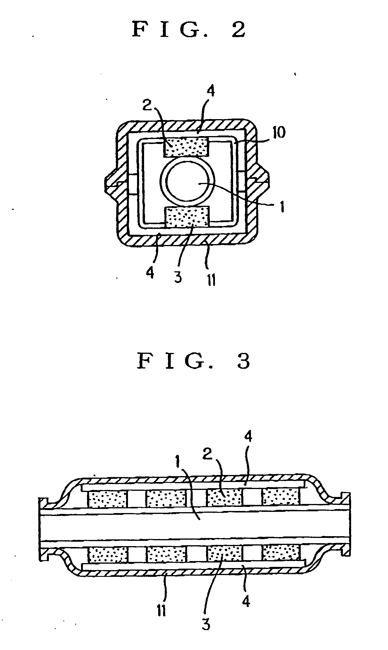
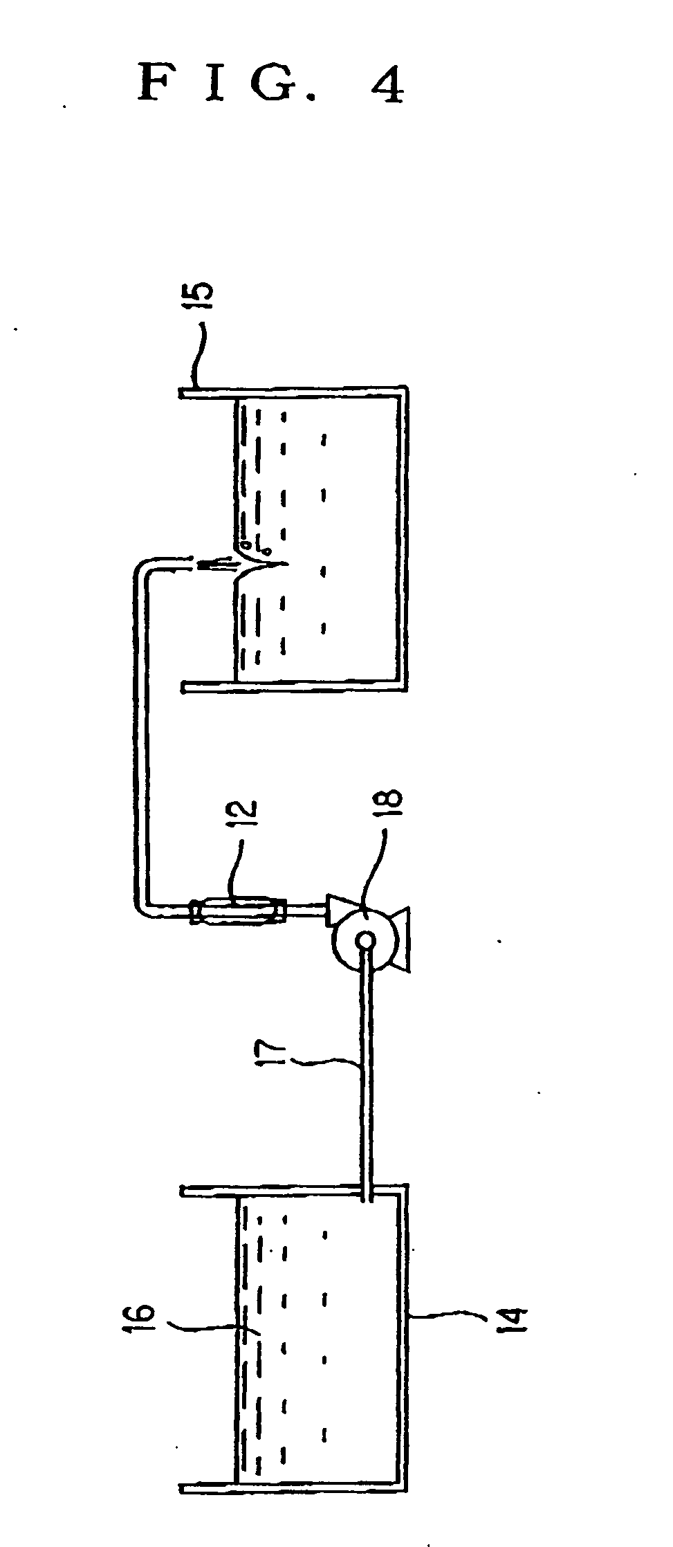
[0023] An activating apparatus according to the present embodiment is described in detail below with reference to the drawings.

[0024]FIG. 1 is a perspective section view illustrating the internal structure of a water activating apparatus according to the present invention.

[0025] In FIG. 1, 1 denotes a water flow pipe, 2 denotes an N pole of a permanent magnet, 3 denotes an S pole of another permanent magnet, 4 denotes concave yokes, 5 denotes ends of each concave yoke 4, 6 denotes polarities transferred to the ends of the concave yokes 4, 7 denotes a direction of magnetic lines of force, 8 denotes a direction of a flow of water, 9 denotes a direction of an electromotive current, and 10 denotes a non-magnetic conductive metal layer.

[0026] The N pole 2 of the permanent magnet and the S pole 3 of the other permanent magnet are vertically arranged above and below the water flow tube 1 so as to be opposed to each other. The concave yokes 4 are formed by molding magnetic metal or magne...


PUM

PropertyMeasurementUnit
Flow rateaaaaaaaaaa
Electrical conductoraaaaaaaaaa
Electric potential / voltageaaaaaaaaaa

Abstract

The present invention provides a water activating apparatus having a relatively simple structure without the possibility of water leakage and achieving highly efficient activation. An N pole of the permanent magnet and an S pole of the other magnet are vertically arranged above and below a water flow tube so as to be opposed to each other. Concave yokes are formed by molding magnetic metal or magnetic ceramic, with one yoke being attached to encase the N pole of the permanent magnet and the other yoke being attached to encase the S pole of the other permanent magnet. The vertically-arranged concave yokes have a gap therebetween so as not to make a contact at their ends with each other. Furthermore, a non-magnetic conductive metal layer is provided inside the concave yokes. Water is caused to pass through the water flow tube in a direction perpendicular to a direction of magnetic lines of force and a direction of an electromotive current.

Description

BACKGROUND OF THE INVENTION [0001] 1. Field of the Invention [0002] The present invention relates to methods and apparatuses for activating water and, particularly, to a method of activating water over a wide range from supplied clean water and gray water to drain water and an apparatus for activating such water. [0003] 2. Description of the Background Art [0004] A scheme of activating water by splitting molecular population of water with the use of a magnetic force to reduce the size of a cluster (molecular assembly) of water has been well known. For example, there have been a system for activation in which water reserved in a reservoir is processed by a filtration unit and a magnetic processing unit (refer to Japanese Patent Laid-Open Publication No. 2002-254082, pp. 2-6, FIG. 1), an apparatus for activating a flow of water in which a permanent magnet is attached to the outside of a water flow tube and an image magnet is formed symmetrically to the surface of the water flow tube (...

Claims


Application Information

Patent Timeline
IPC IPC(8): A63B37/12
CPCC02F1/481C02F1/005
Inventor MOCHIZAI, TADASHI
Owner MOCHIZAI TADASHI
Why Eureka
Try Eureka