Collision detection system and method of estimating target crossing location

a detection system and collision detection technology, applied in the field of collision detection of objects, can solve the problems of inability to provide additional information such as the crossing location of the vehicle, and the relative complexity and cost of the sensor arrangement, and achieve the effect of enhancing countermeasures

Active Publication Date: 2005-09-08
CARRUM TECH LLC
View PDF15 Cites 30 Cited by
  • Summary
  • Abstract
  • Description
  • Claims
  • Application Information

AI Technical Summary

Benefits of technology

[0008] Accordingly, the collision detection system and method of estimating target crossing location of the present invention advantageously estimates the crossing location of an object without requiring a complex and costly sensor arrangement. By knowing the target crossing location, the present invention advantageously allows for enhanced countermeasures to be employed on a vehicle.

Problems solved by technology

The sensor arrangement employed in such conventional systems generally requires a relatively complex and expensive sensor arrangement employing multiple sensors that are required to measure the azimuth angle of the object, relative to the host vehicle, in addition to obtaining range and range rate measurements of the object.
While the aforementioned approaches employing a single radar sensor are well suited to estimate the miss distance of an object, additional information such as the crossing location with respect to the vehicle is generally not available.

Method used


Image

  • Collision detection system and method of estimating target crossing location
  • Collision detection system and method of estimating target crossing location
  • Collision detection system and method of estimating target crossing location

Examples


first embodiment

[0037] Referring to FIG. 6, a routine 80 for estimating the crossing location C of a target object is shown according to the present invention. Routine 80 employs the data plotted in the W-plane for both of sensors 12A and 12B. One example of data plotted in the W-plane for both of sensors 12A and 12B is shown in FIG. 7. As seen in FIG. 7, a least-squares line 66A is drawn through the data representing measurements taken with the first sensor 12A. Likewise, a least-squares line 66B is determined with respect to the data representing measurements taken with the second sensor 12B.

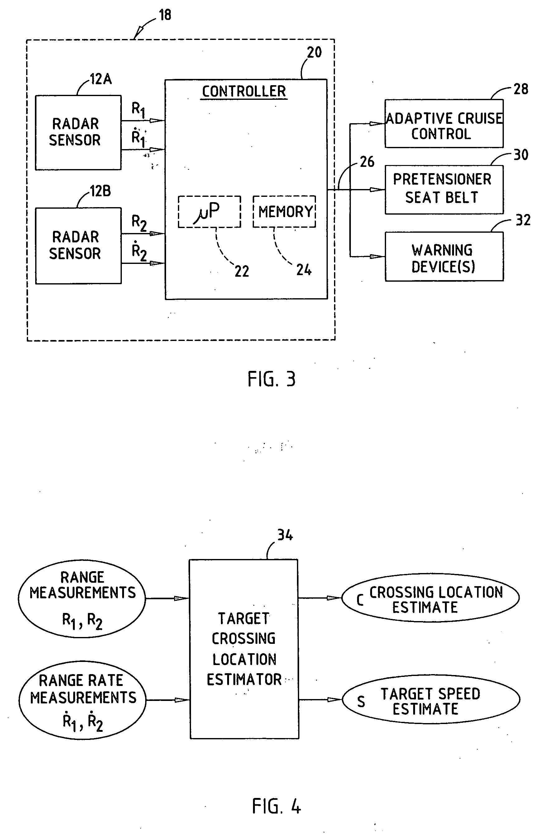
[0038] Routine 80 begins at step 82 and proceeds to get the current range measurement R1 and R2 and range rate measurements {dot over (R)}1 and {dot over (R)}2 sensed by first and second radar sensors in step 84. Routine 80 may associate data with the particular target object by way of an object tracker. The object tracker tracks each object based on the combination of range and range rate measurements taken ...

second embodiment

[0045] Referring to FIGS. 8 and 9, a time-domain approach to estimating the crossing location C of a target object 16 is shown according to the present invention. The time-domain approach to estimating the crossing location employs an estimator 34′ having tracking filters 100 and 102 coupled to corresponding radar sensors 12A and 12B to produce a range R estimate for each sensor. The tracking filters 100 and 102 may also receive range rate {dot over (R)}; however, the tracking filters 100 and 102 may operate without range rate. The estimator 34′ further includes mathematical square functions 104 and 106 for calculating the mathematical square of the outputs of tracking filters 100 and 102, respectively. A subtractor 108 computes the difference between the outputs of square functions 104 and 106. Additionally, estimator 34′ employs a divider 110 for dividing the computed difference by twice the separation distance (2d) of sensors 12A and 12B. The output of divider 110 is applied to a...


PUM


Abstract

A collision detection system and method of estimating a crossing location are provided. The system includes a first sensor for sensing an object in a field of view and sensing a first range defined as the distance between the object and the first sensor. The system also includes a second sensor for sensing the object in the field of view and sensing a second range defined by the distance between the object and the second sensor. The system further includes a controller for processing the first and second range measurements and estimating a crossing location of the object as a function of the first and second range measurements. The crossing location is estimated using range and range rate in a W-plane in one embodiment and using a time domain approach in another embodiment.

Description

TECHNICAL FIELD [0001] The present invention generally relates to object collision detection and, more particularly, relates to a collision detection system and method of estimating the crossing location of the object. BACKGROUND OF THE INVENTION [0002] Automotive vehicles are increasingly being equipped with collision avoidance and warning systems for predicting potential collisions with external objects, such as another vehicle or a pedestrian. Upon detecting a potential collision, such systems are capable of initiating an action to avoid the collision, minimize impact with the object, and / or provide a warning to the vehicle operator. Adaptive cruise control systems have been proposed to track a leading vehicle and automatically control the speed of the following vehicle. The ability to accurately predict an upcoming collision also enables a vehicle controller to control and deploy safety-related devices on the host vehicle. For example, upon predicting an anticipated collision or...

Claims


Application Information

Patent Timeline
Patent Type & Authority Applications(United States)
IPC IPC(8): G01S13/00G01S13/58G01S13/72G01S13/87G01S13/931
CPCG01S13/588G01S13/726G01S13/878G01S2013/9389G01S2013/9375G01S2013/9321G01S13/931G01S2013/93275G01S2013/93271
Inventor SCHIFFMANN, JAN K.PUNATER, SANDEEP D.
Owner CARRUM TECH LLC
Why Eureka
Try Eureka