Collision detection system and method of estimating target crossing location
a detection system and collision detection technology, applied in the field of collision detection of objects, can solve the problems of affecting the accuracy of collision detection, the relative complexity and cost of sensor arrangement, and the inability to provide additional information such as the crossing location of the vehicle, so as to achieve enhanced countermeasures
- Summary
- Abstract
- Description
- Claims
- Application Information
AI Technical Summary
Benefits of technology
Problems solved by technology
Method used
Image
Examples
first embodiment
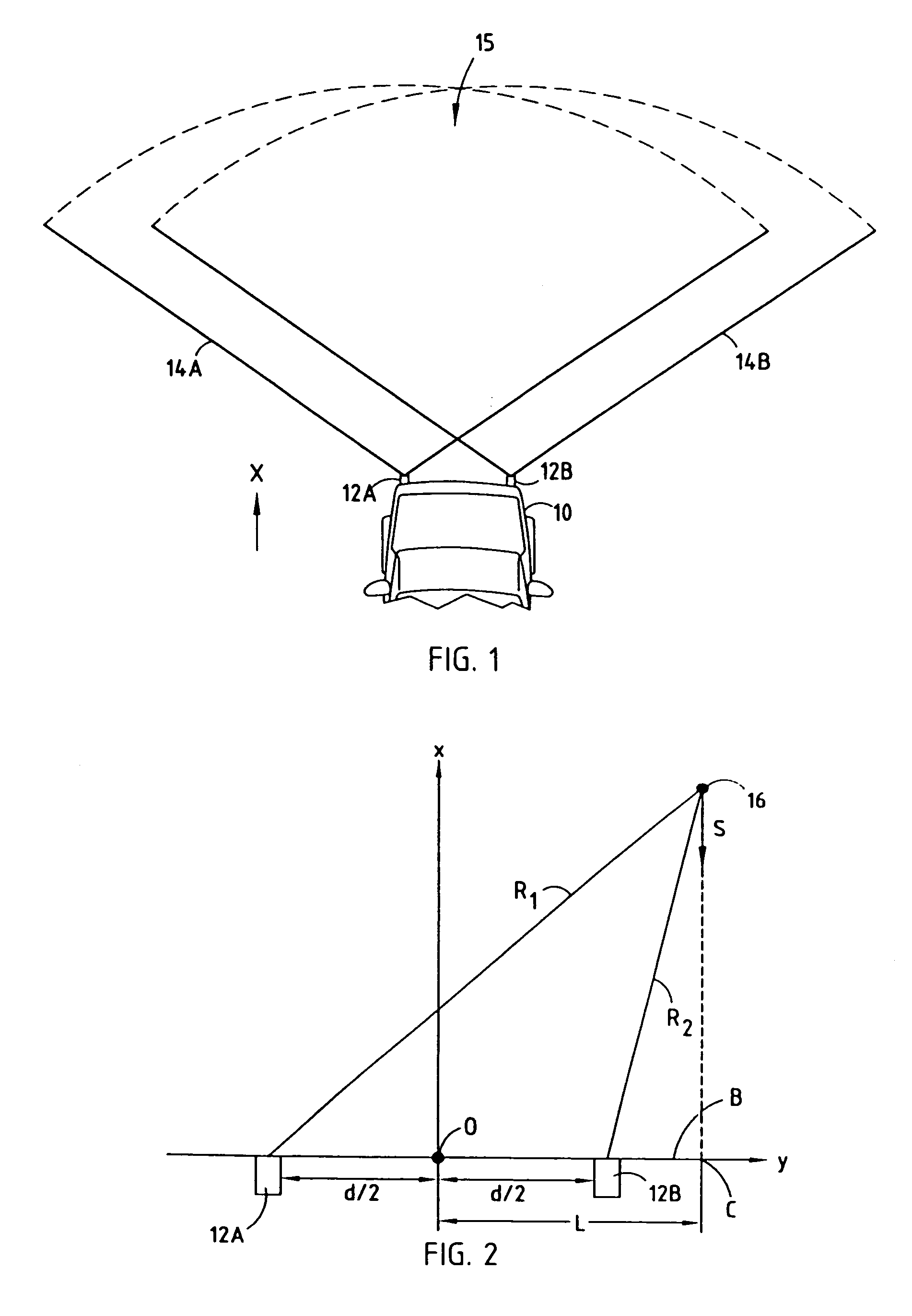
[0038]Referring to FIG. 6, a routine 80 for estimating the crossing location C of a target object is shown according to the present invention. Routine 80 employs the data plotted in the W-plane for both of sensors 12A and 12B. One example of data plotted in the W-plane for both of sensors 12A and 12B is shown in FIG. 7. As seen in FIG. 7, a least-squares line 66A is drawn through the data representing measurements taken with the first sensor 12A. Likewise, a least-squares line 66B is determined with respect to the data representing measurements taken with the second sensor 12B.
[0039]Routine 80 begins at step 82 and proceeds to get the current range measurement R1 and R2 and range rate measurements {dot over (R)}1 and {dot over (R)}2 sensed by first and second radar sensors in step 84. Routine 80 may associate data with the particular target object by way of an object tracker. The object tracker tracks each object based on the combination of range and range rate measurements taken wi...
second embodiment
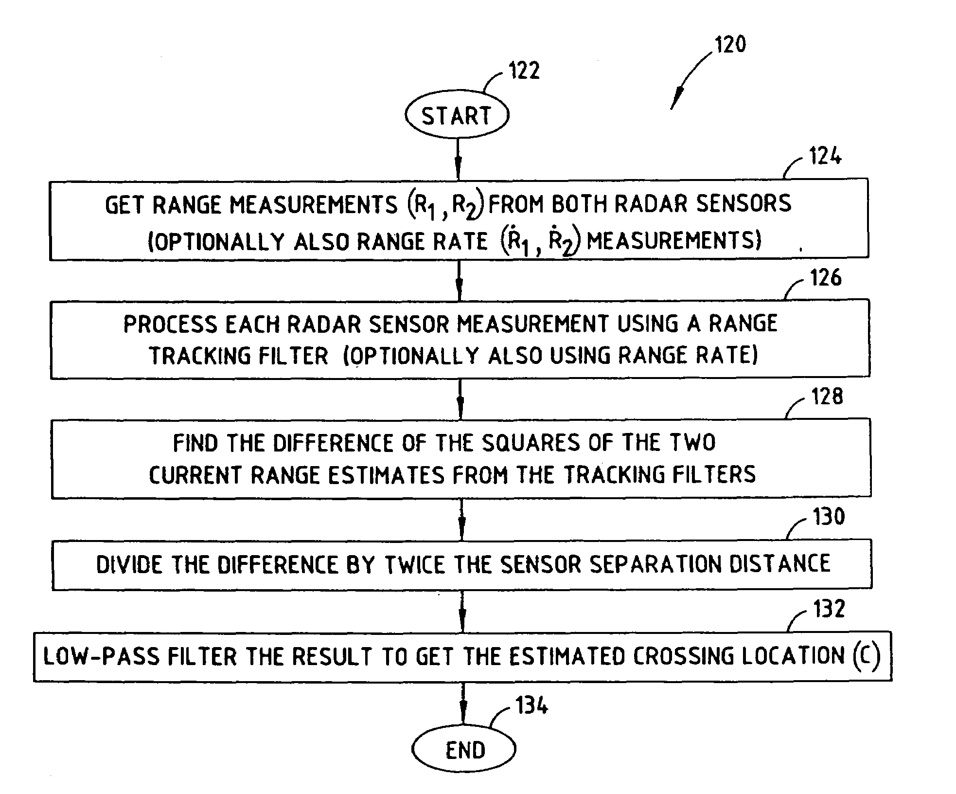
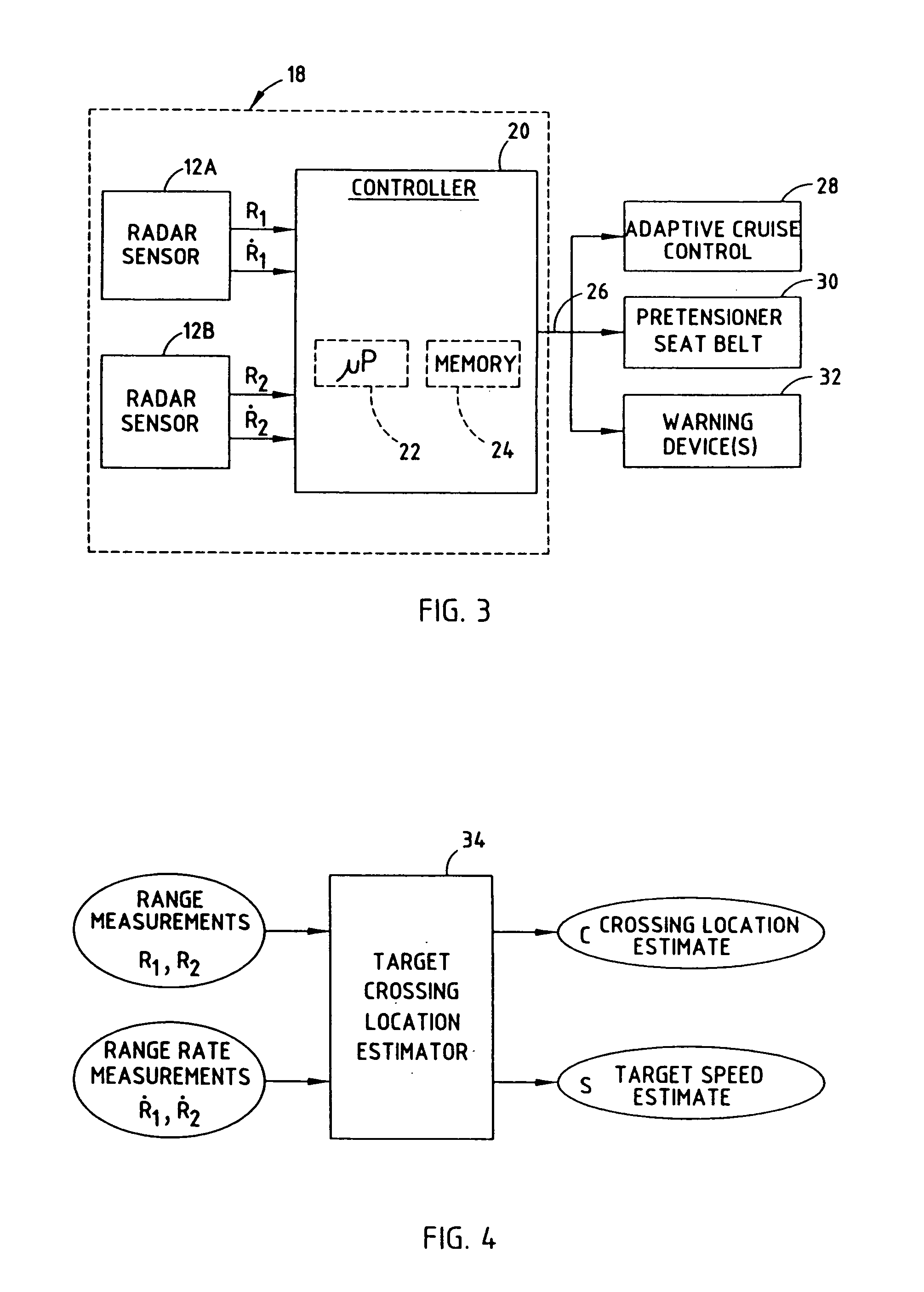
[0046]Referring to FIGS. 8 and 9, a time-domain approach to estimating the crossing location C of a target object 16 is shown according to the present invention. The time-domain approach to estimating the crossing location employs an estimator 34′ having tracking filters 100 and 102 coupled to corresponding radar sensors 12A and 12B to produce a range R estimate for each sensor. The tracking filters 100 and 102 may also receive range rate {dot over (R)}; however, the tracking filters 100 and 102 may operate without range rate. The estimator 34′ further includes mathematical square functions 104 and 106 for calculating the mathematical square of the outputs of tracking filters 100 and 102, respectively. A subtractor 108 computes the difference between the outputs of square functions 104 and 106. Additionally, estimator 34′ employs a divider 110 for dividing the computed difference by twice the separation distance (2d) of sensors 12A and 12B. The output of divider 110 is applied to a ...
PUM
 Abstract
Description
Claims
Application Information
 - R&D
- Intellectual Property
- Life Sciences
- Materials
- Tech Scout
- Unparalleled Data Quality
- Higher Quality Content
- 60% Fewer Hallucinations
Browse by: Latest US Patents, China's latest patents, Technical Efficacy Thesaurus, Application Domain, Technology Topic, Popular Technical Reports.
© 2025 PatSnap. All rights reserved.Legal|Privacy policy|Modern Slavery Act Transparency Statement|Sitemap|About US| Contact US: help@patsnap.com


