
Cutting system construction for electric dry foil shavers

a cutting system and foil shaver technology, applied in the field of electric dry shavers, can solve the problems of consuming the public, requiring more time and inconvenience than most individuals are willing or capable of incurring, and the use of razors or other systems is extremely inconvenient for removing or shaving short hair or stubble, so as to achieve high-efficiency and effective cutting, long-term, high-efficiency and efficient cutting capabilities

Inactive Publication Date: 2005-09-15
ROVCAL +1
View PDF13 Cites 6 Cited by
  • Summary
  • Abstract
  • Description
  • Claims
  • Application Information

AI Technical Summary

Benefits of technology

[0018] By employing the present invention, all of the difficulties and drawbacks found with the prior art constructions are completely eliminated and a substantially improved, highly effective, and long-lasting cutting blade assembly is realized. Furthermore, the present invention provides a cutting blade assembly which is substantially less expensive to manufacture, assemble, and employ in a shaver when compared to prior art constructions.
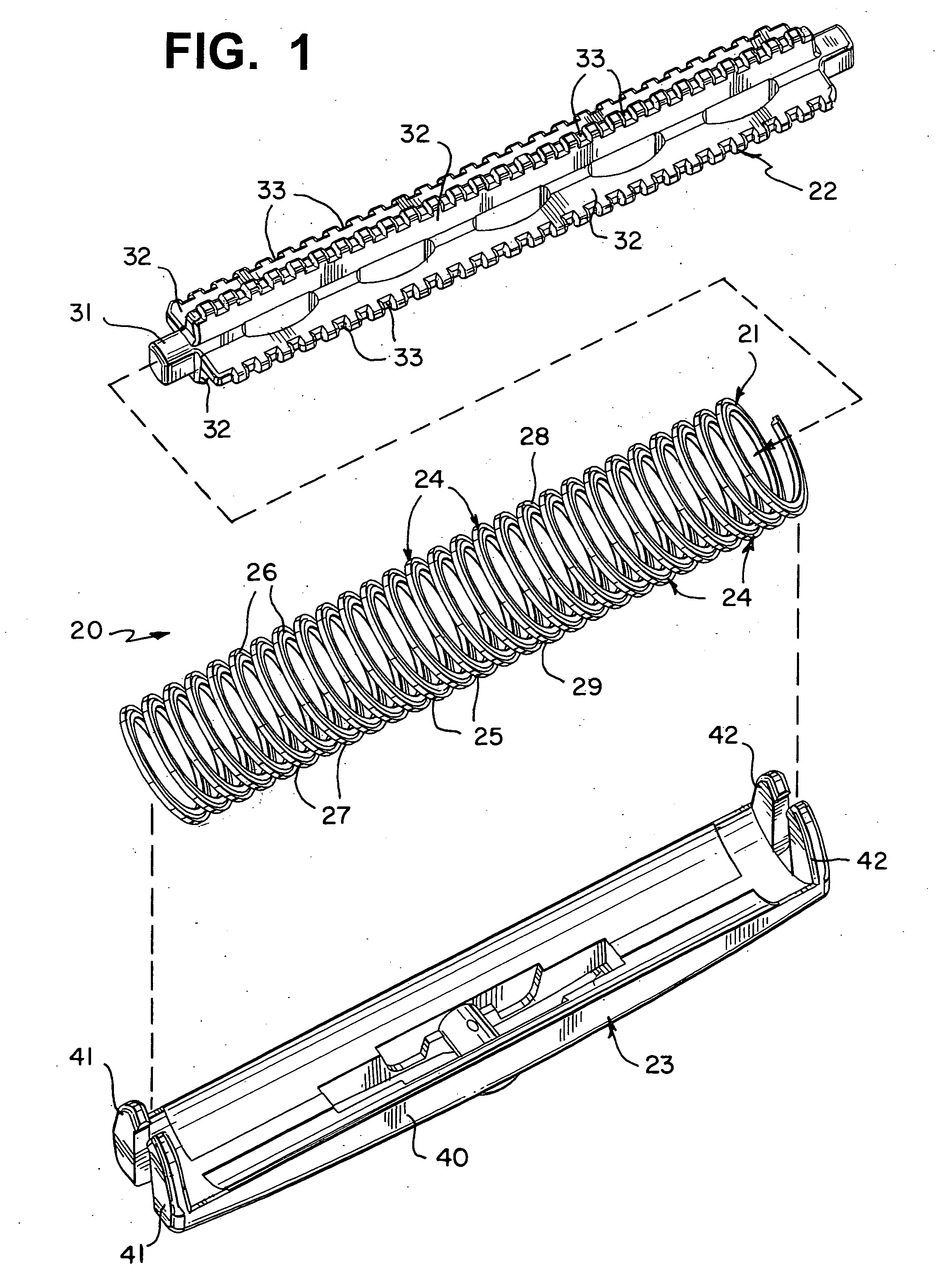
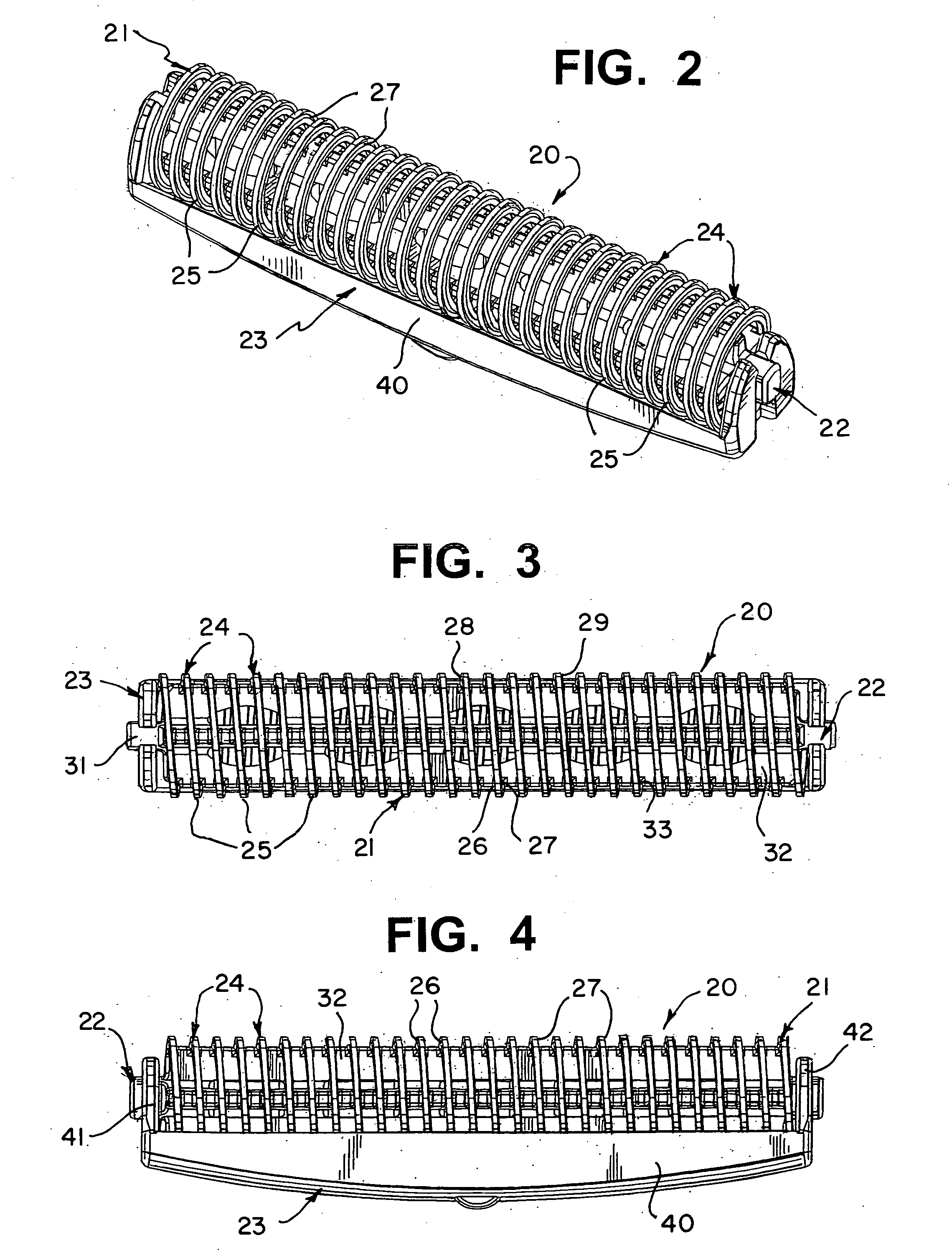
[0019] In accordance with the present invention, a unique highly effective, and low-cost cutting blade assembly is attained by employing a substantially continuous, arcuately curved, helical-shaped, spring-like coil or ribbon as the cutting element which is securely mounted and supportingly retained in a holding member. In the preferred construction, an elongated coil holding bar is employed for securely holding and retaining the entire length of the helical-shaped, spring-like coil / ribbon, imparting the required rigidity for enabling the elongated coil / ribbon to function in the desired manner.
[0020] In the preferred configuration, the elongated bar incorporates a plurality of radially extending panel members mounted to a central hub, with the panel members being constructed for enabling the elongated, helically shaped coil / ribbon to be quickly and easily mounted thereon. In this way, the cutting blade component is quickly and easily fully assembled and mounted to the shaver in cooperating engagement with the apertured foil or mesh screen thereof.
[0022] By employing the construction detailed above, a highly efficient and effective cutting blade assembly is realized which is capable of providing long term, highly effective and efficient cutting capabilities in any desired apertured foil or mesh screen shaver. In addition, the cutting blade assembly is constructed and fully assembled quickly and easily, without requiring numerous small components and tedious, costly assembly time. Consequently, an easily produced, low-cost, cutting blade assembly is achieved without in any way compromising the desired efficacy and efficiency.
[0023] A further feature preferably incorporated into the cutting blade assembly of this invention is the construction of the helically shaped coil / ribbon with an outer edge which is constructed for optimizing cutting efficiency. In this regard, in one embodiment, the outer edge of the helically shaped coil / ribbon is constructed with sharp edges for providing the desired cutting efficacy.
[0024] In the preferred embodiment, however, the outer edge of the helical shaped coil / ribbon is constructed with inwardly sloping or slanted side edges, providing an outer edge which essentially tapers downwardly as one moves from the outer edge inwardly. In this way, as the outer edge of the helical shaped coil / ribbon wears due to frictional engagement with the aperture foil or mesh screen, the cutting angle formed between the side edge and the terminating outer surface of the helical shaped coil / ribbon remains at a sharp angle, thereby assuring long term, continuous cutting effectiveness.

Problems solved by technology

In general, the consuming public has found that the use of razors or other systems is extremely inconvenient for removing or shaving short hair or stubble, as is commonly found in men's beards and women's legs.
The discomfort as well as the time consumed in using shaving cream, soaps, and gels in order to provide a medium for which a razor can be used, requires more time and inconvenience than most individuals are willing or capable of incurring.
Furthermore, the cost of maintaining a sufficient supply of these products creates an additional burden.
However, in spite of these product changes, difficulties have continued to exist in providing optimal results with optimum comfort.
Although this dry shaving cutting system has proven to be extremely effective, as compared to other dry shaving products, particular areas of difficulty continue to exist.
One such area is found in the expense and difficulty which has continued to exist in manufacturing the cutting blades and the cutting blade assembly.
Although this construction has become extremely popular and is widely used, the cost of manufacturing each of the plurality of independent cutting blade elements and affixing each of the cutting blade elements to the elongated rod has proven to be an extremely time-consuming and costly component to manufacture and assemble.
However, although this problem has existed for many years, prior art constructions have been incapable of achieving an alternate construction which is capable of providing all of the qualities and performance characteristics inherent in this prior art construction.
However, due to the continuous, reciprocating movement, the edges of the cutting blades become worn, thereby losing their cutting efficiency.
As a result, replacement of the entire cutting blade assembly is needed, thereby requiring the consumer to incur additional expenses.

Method used


Image

  • Cutting system construction for electric dry foil shavers
  • Cutting system construction for electric dry foil shavers
  • Cutting system construction for electric dry foil shavers

Examples


Embodiment Construction

[0035] By referring to FIGS. 1-8, along with the following detailed disclosure, the construction of the preferred embodiment of cutting blade assembly and support system 20 of the present invention can best be understood. However, is also to be understood that alternate constructions or variations of this invention can be made without departing from the scope of this invention. Consequently, the following disclosure, along with FIGS. 1-8, are provided for exemplary purposes only and are not intended as a limitation of the present invention.

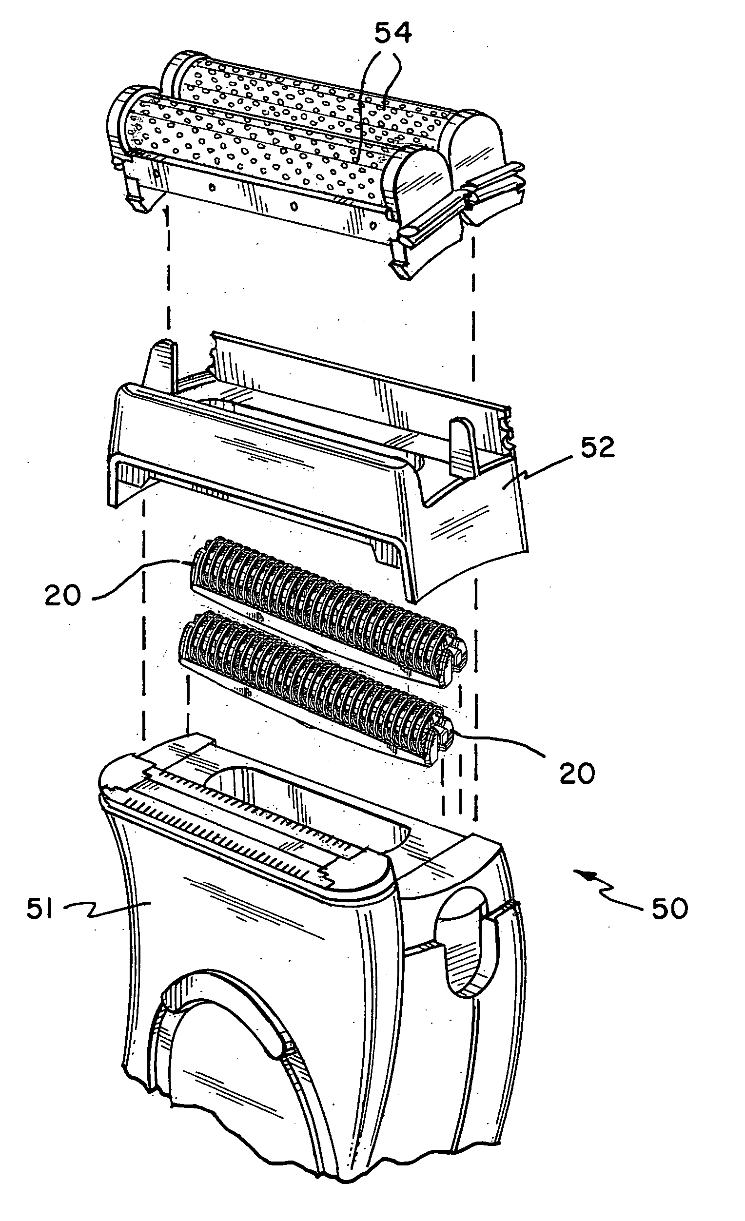
[0036] In a typical construction, cutting blade assembly and support system 20 of the present invention is employed in an electric shaver which incorporates an apertured foil or mesh screen in order to achieve the desired cutting action. In this regard, as shown in FIG. 8, a generally conventional electric shaver 50 is shown, for exemplary purposes only, comprising housing 51 to which guard / cover support base 52 is removable and mounted. In addit...


PUM


Abstract

By providing a substantially continuous, arcuately curved, helical-shaped, spring-like coil or ribbon as the cutting element and securely mounting and retaining the coil / ribbon in a holding member, a substantially improved, highly effective, and long-lasting cutting blade assembly is realized. Furthermore, the cutting blade assembly of this invention is substantially less expensive to manufacture, assemble, and employ in a shaver when compared to prior art constructions. In the preferred construction, an elongated coil holding bar is employed for securely holding and retaining the entire length of the helical-shaped, spring-like coil / ribbon, imparting the required rigidity for enabling the elongated coil / ribbon to function in the desired manner. Furthermore, in the preferred configuration, the elongated bar incorporates a plurality of radially extending panel members mounted to a central hub, with the panel members being constructed for enabling the elongated, helically shaped coil / ribbon to be quickly and easily mounted thereon.

Description

RELATED APPLICATIONS [0001] This application is related to U.S. Provisional Patent Application Ser. No. 60 / 553,245, filed Mar. 15, 2004, entitled Improved Cutting System Construction for Electric Dry Foil Shavers. TECHNICAL FIELD [0002] This invention relates to electric dry shavers and, more particularly, to improved cutting systems for shavers employing aperture foils. BACKGROUND ART [0003] Over the last many years, both men and women have been increasingly drawn to the advantages provided by electric dry shavers. In general, the consuming public has found that the use of razors or other systems is extremely inconvenient for removing or shaving short hair or stubble, as is commonly found in men's beards and women's legs. In addition, with the ever increasing time constraints and commitments individuals typically encounter, a fast and effective shaving system is most desirable. [0004] The discomfort as well as the time consumed in using shaving cream, soaps, and gels in order to pr...

Claims


Application Information

Patent Timeline
Patent Type & Authority Applications(United States)
IPC IPC(8): B26B19/04B26B19/14
CPCB26B19/044B26B19/04
Inventor ANDREW, MICHAELGARBARINO, ROBERT
Owner ROVCAL
Learn More