Drying machine

a technology of drying machine and drying chamber, which is applied in the direction of drying machine, lighting and heating apparatus, furniture, etc., can solve the problems of increasing energy consumption for drying the matter to be dried, increasing energy costs such as electricity and gas charges, and reducing the service life of the machine, so as to facilitate assembly operation and enhance the maintenance property

Inactive Publication Date: 2005-09-15
SANYO ELECTRIC CO LTD
View PDF4 Cites 34 Cited by
  • Summary
  • Abstract
  • Description
  • Claims
  • Application Information

AI Technical Summary

Benefits of technology

[0008] The present invention has been developed to solve the conventional problem, and an object thereof is to provide a drying machine capable of reducing vibration generated by rotation of a rotary drum.

Problems solved by technology

On the other hand, in the drying machine using the electric heater or the gas burning heater, since outside air having a low temperature outside the housing chamber and containing humidity is used in high-temperature air sent into the housing chamber, long time is required until the matter to be dried dries.
Therefore, energy consumption for drying the matter to be dried increases, and there has been a problem that energy costs such as electricity and gas charges soar.

Method used


Image

  • Drying machine
  • Drying machine
  • Drying machine

Examples


embodiment 1

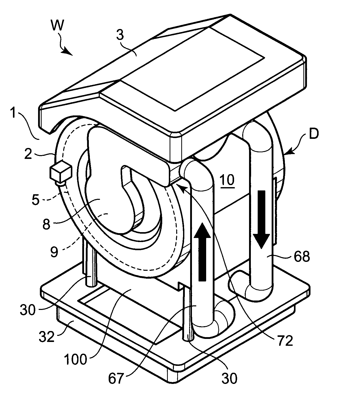
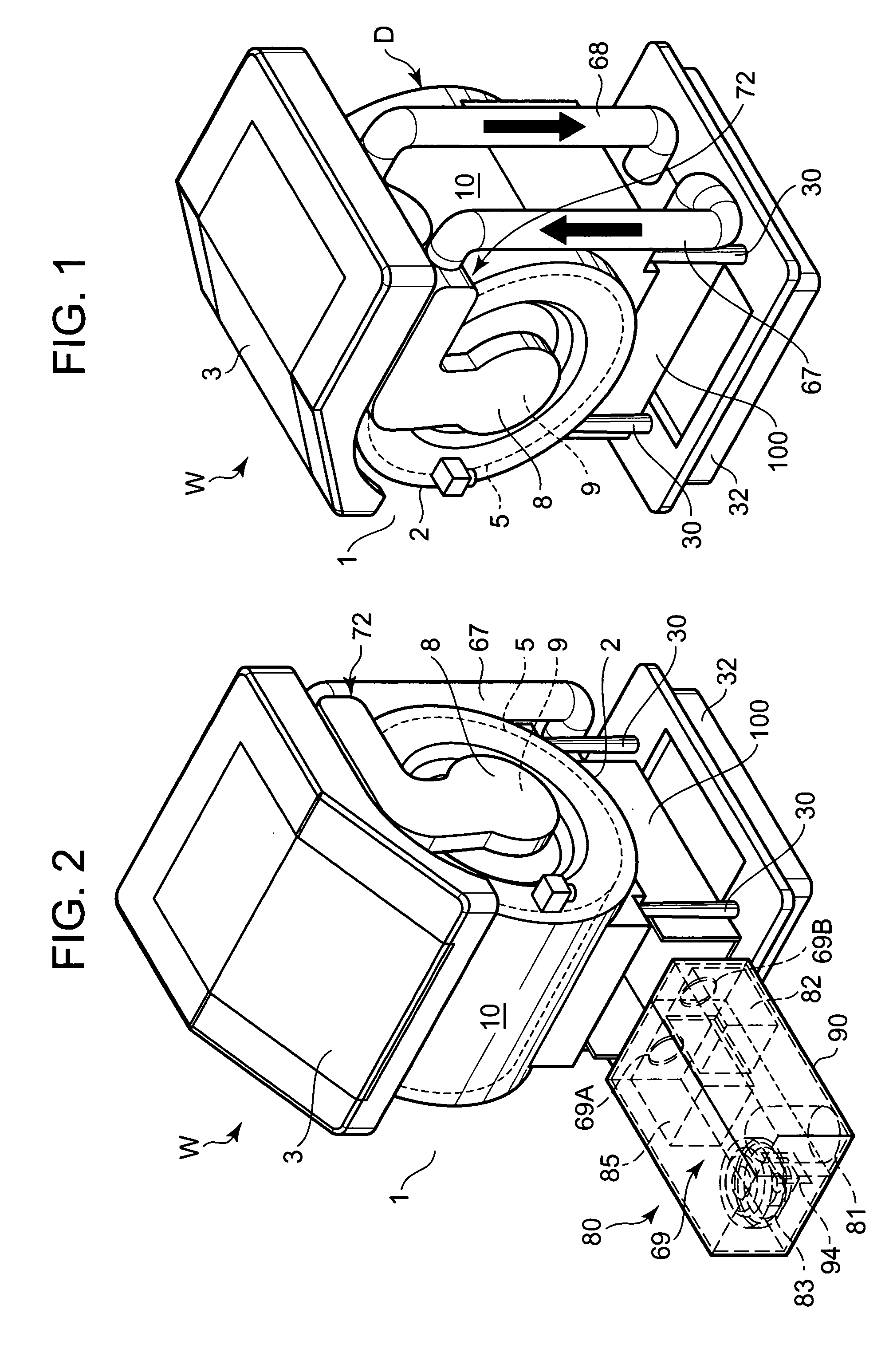
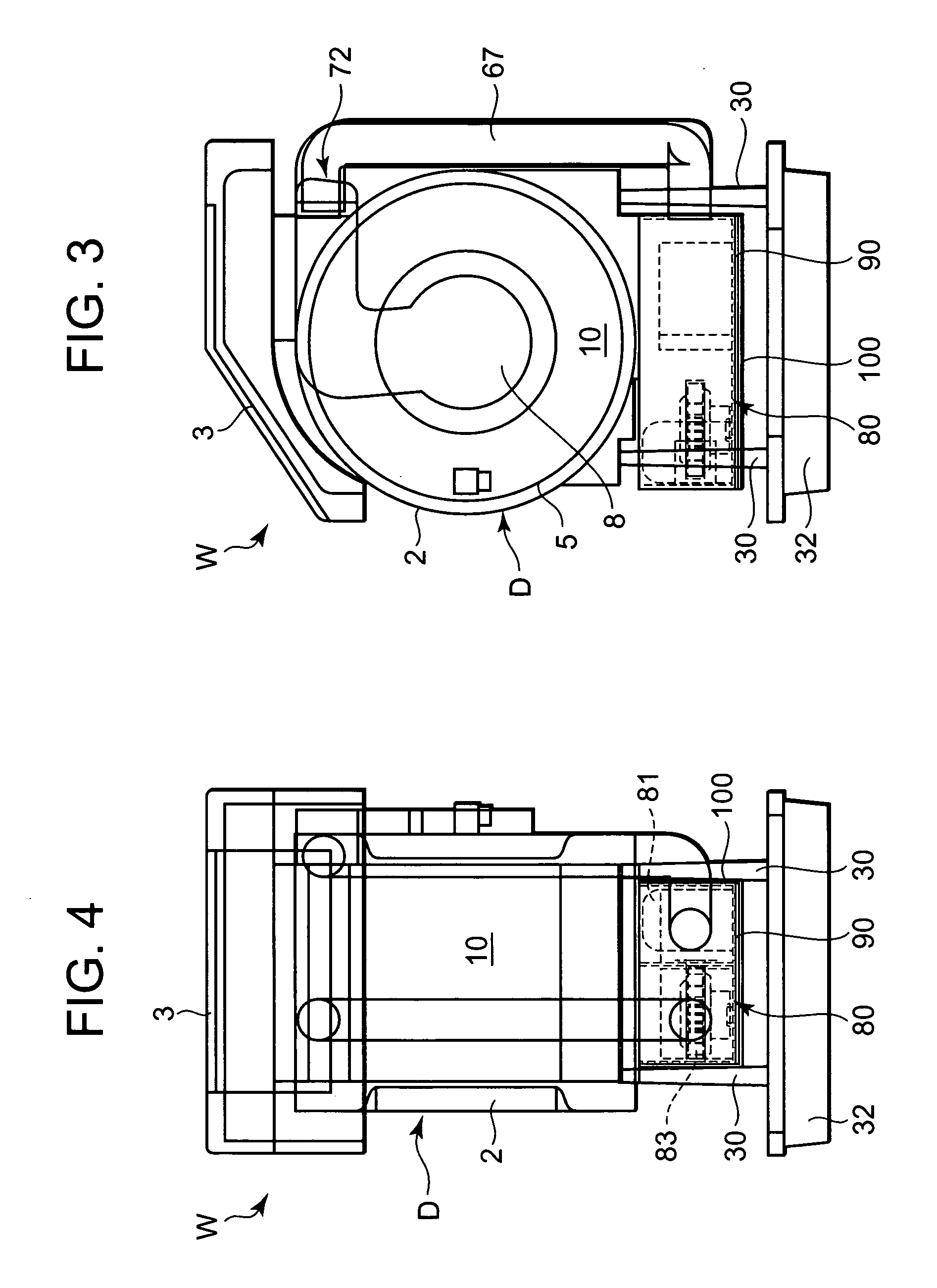
[0042]FIG. 1 is an inner constitution diagram of a washing / drying machine W which executes a washing operation and a drying operation after ending the washing operation according to one embodiment of a drying machine to which the present invention is applied, FIG. 2 is an inner constitution diagram of the washing / drying machine W in a state in which a drying unit is taken out, and FIGS. 3 and 4 are sectional views of the washing / drying machine W.

[0043] The washing / drying machine W of the present embodiment is used for washing and drying a matter to be washed such as clothing (this matter to be washed constitutes a matter to be dried in the drying operation). An open / close door 3 for inserting / removing the matter to be washed is attached to an upper surface middle part of a main body 1 (a case of the main body 1 is seen through in the drawing) forming an outer body. An operation panel (not shown) on which various operation switches and display portions are arranged is disposed on th...

embodiment 2

[0085] Next, another embodiment of a drying machine to which the present invention is applied will be described with reference to FIGS. 12 and 13. It is to be noted that in FIGS. 12 and 13, components denoted with the same numerals as those of FIGS. 1 to 9 produce similar effects.

[0086] In FIG. 12, reference numeral 120 denotes an installation hole for installing a drying unit 80, and the installation hole 120 is formed in a base 32. The installation hole 120 has an opening in the front face of the base 32, and an insulating box member 90 of the drying unit 80 is drawably attached from the opening in the front face. A plurality of trenches 104 . . . are formed in the bottom part of the installation hole 120 in the same manner as in the installation base 100. By the trenches 104 . . . when the insulating box member 90 is inserted into the installation hole 120, rollers 102 . . . attached to the lower part of the insulating box member 90 are held.

[0087] Moreover, two holes (not show...


PUM


Abstract

An object is to provide a drying machine capable of reducing vibration generated by rotation of a rotary drum. There is provided a drying machine which executes a drying operation of a matter to be dried in a housing chamber constituted in an inner drum of a drum main body constituted of an outer drum and the inner drum disposed inside the outer drum, the drying machine comprising: a refrigerant circuit constituted by successively piping / connecting a compressor, a gas cooler, an expansion valve, and an evaporator in an annular shape; and an air circulation path for discharging air whose heat has been exchanged with the gas cooler into the housing chamber by a blower fan, and allowing the air which has passed through the housing chamber to exchange the heat with the evaporator, wherein a drum main body is attached to a base via a suspension, and the compressor is attached to a lower part of the drum main body.

Description

BACKGROUND OF THE INVENTION [0001] The present invention relates to a drying machine which executes a drying operation of a matter to be dried in a housing chamber constituted in a rotary drum of a drum main body. [0002] This type of drying machine has heretofore comprised: a drying unit constituted of an electric heater, a heat source of a gas burning heater, a fan, and a driving motor in a main body; and a rotary drum in which a housing chamber for housing a matter to be dried is formed. Moreover, air blown by a fan (blowing means) is heated by the electric heater or the gas burning heater, and thereafter blown to the housing chamber in the rotary drum to dry the matter to be dried in the housing chamber. [0003] In this drying machine, a drying unit is independently disposed above the rotary drum, the drying unit and the rotary drum are connected to a flexible duct having flexibility, and vibration transmitted to the drying unit from the rotary drum is reduced (see, e.g., Japanese...

Claims


Application Information

Patent Timeline
Patent Type & Authority Applications(United States)
IPC IPC(8): D06F58/02D06F58/20F26B3/00F26B21/06
CPCD06F58/206D06F58/20
Inventor TOMOCHIKA, KAZUYOSHIONO, KOJI
Owner SANYO ELECTRIC CO LTD
Why Eureka
Try Eureka