
Glass run structure for vehicle

Inactive Publication Date: 2005-09-15
NISHIKAWA RUBBER
View PDF7 Cites 14 Cited by
  • Summary
  • Abstract
  • Description
  • Claims
  • Application Information

AI Technical Summary

Benefits of technology

[0011] According to the glass run structure of the present invention, effects such as the following are obtained. A simplified glass run structure configuration with reduced weight can be achieved because a lower sash is unnecessary. Unlike a conventional glass run structure provided with a lower sash, operations to mount the lower sash and attach the glass run to the lower sash become unnecessary, thereby simplifying the operation to mount the glass run in the door panel. It is also possible to inhibit a squealing noise and wear of the inner lip, which are generated by the inner lip strongly pressing against the window glass due to fitting variations when mounting the lower sash to the door panel. Compared to a glass run body made entirely of metal, the glass run body can be more easily bent to match a curved surface of the window glass, even though a portion of the glass run body may be made of metal.
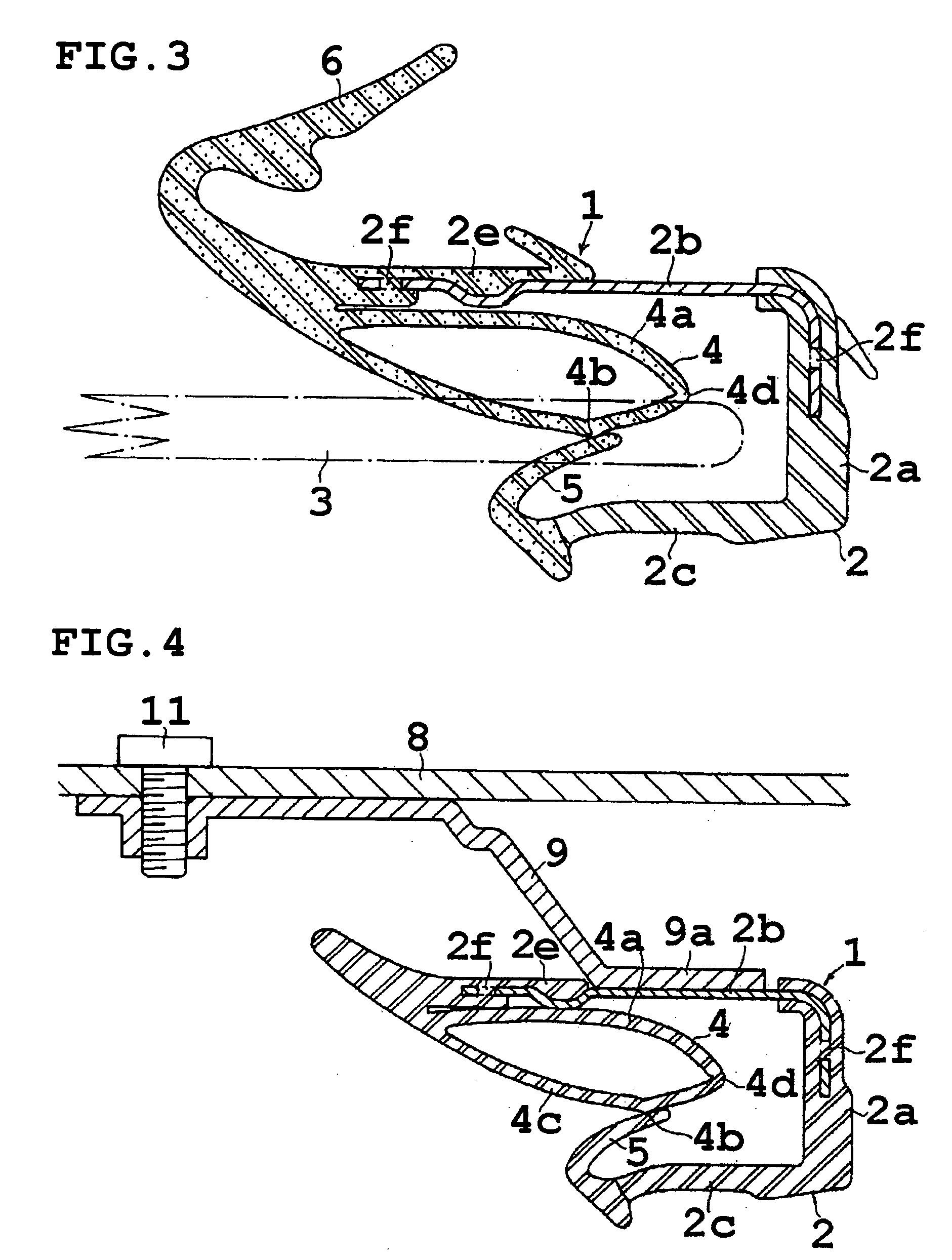
[0022] The bracket of the above glass run structure preferably has an attachment portion extending along the metal portion or the metal core. Having the attachment portion next to the metal portion or the metal core makes the glass run more resistant to deformation, thus ensuring stable support of the window glass.

Problems solved by technology

Thus as shown in FIG. 11, contact between both sashes may be misaligned due to fitting variations.
This leads to problems such as a so-called squealing noise caused by the window glass 32 sliding against the inner lip 37 when raised or lowered, and wear of the inner lip 37.
Furthermore, the conventional glass run structure tends to become complicated, because the lower sash 34 is mounted to the door panel 31 by fixing the top and bottom of the lower sash 34 to the door panel 31 with brackets 38.
Being made of steel, it is not easy to bend the core metal 41.

Method used


Image

  • Glass run structure for vehicle
  • Glass run structure for vehicle
  • Glass run structure for vehicle

Examples


Embodiment Construction

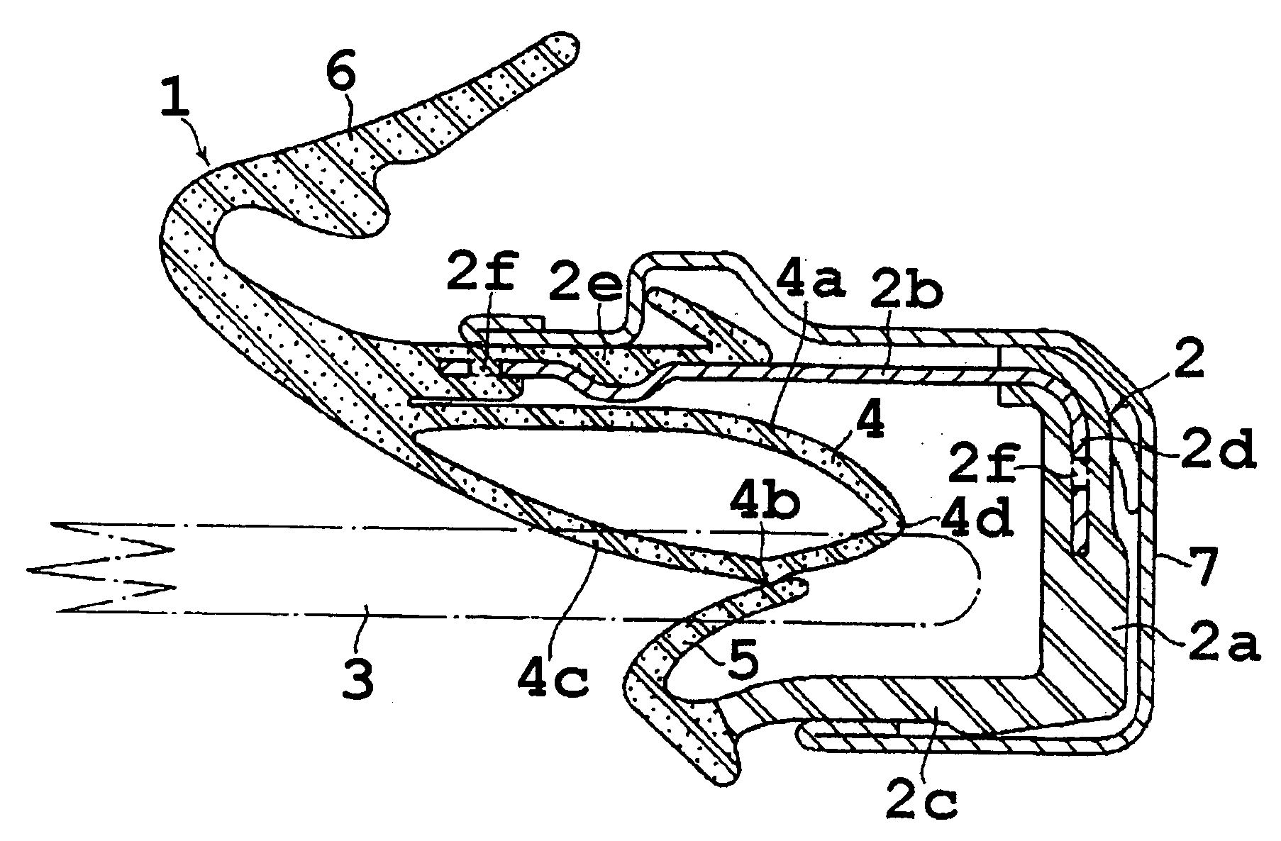
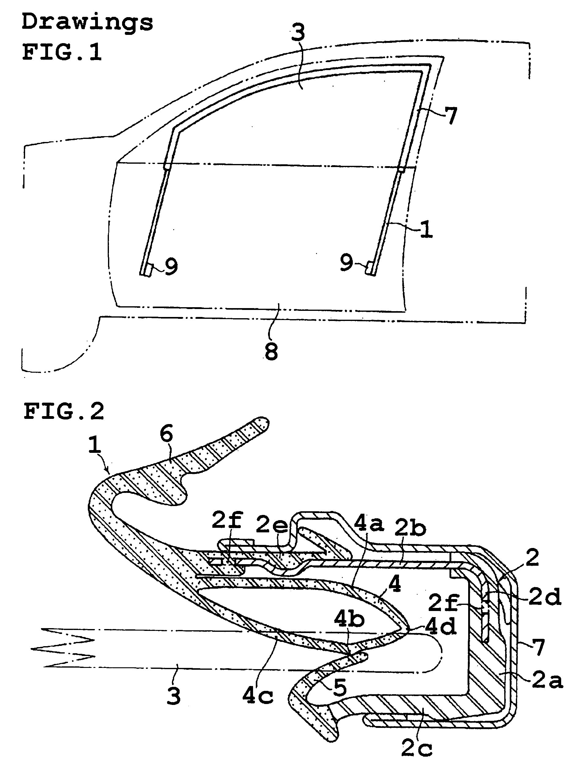
[0037] FIGS. 1 to 4 show a glass run structure according to the present invention. A glass run 1 is formed from a glass run body 2 with a substantially U-shaped cross section, a hollow inner lip 4, an outer lip 5, and a cover lip 6. The glass run body 2 is formed from a bottom 2a and sidewalls 2b and 2c provided on both sides of the bottom. The inner lip 4 extends inward toward the bottom 2a from an end of the sidewall 2b that forms an open end of the glass run body 2. Elastically contacting a window glass 3, the inner lip 4 also seals a clearance with the window glass 3. Likewise, the outer lip 5 extends inward toward the bottom 2a from an end of the sidewall 2c that forms an open end of the glass run body 2, elastically contacts the window glass 3, and seals a clearance with the window glass 3. The cover lip 6 faces away from the end of the sidewall 2b and extends opposite the inner lip 4 to cover an end portion of interior material (not shown). In addition, the inner lip 4 has a ...


PUM


Abstract

A glass run structure for a vehicle door, in which a glass run is formed from a glass run body with a substantially U-shaped cross section, as well as a bottom and sidewalls provided on both sides of the bottom; and a hollow inner lip and an outer lip extending inward from an open end of the glass run body. The sidewall is formed from a steel member with an L-shaped cross section. The glass run is mounted to a sash provided in a window frame of a door panel above a belt line; while in a lower end portion below the belt line, the glass run is fixed by welding to an attachment portion of a bracket that is held by a bolt to the door panel.

Description

BACKGROUND OF THE INVENTION [0001] 1. Field of the Invention [0002] The present invention relates to a glass run structure provided in a vehicle door, which guides a window glass and seals a clearance with the window glass. [0003] 2. Related Art [0004] A glass run structure is generally provided in a vehicle door for guiding a rim of a window glass 32 and sealing purposes as shown in FIG. 9. The glass run structure, as shown in FIGS. 9 and 10, includes a sash 33 provided in a window frame of the door above a belt line B.L., a lower sash 34 extending into a door panel below the belt line B.L., and a glass run 35 mounted in the sash 33 and the lower sash 34. The glass run 35 has a substantially U-shaped cross section, and is formed of resin or rubber such as EPDM. Provided at an open end of the glass run 35 are an outer lip 36 and an inner lip 37, which elastically contact and seal the window glass 32. [0005] In such a conventional glass run structure, the lower sash 34 is formed sepa...

Claims


Application Information

Patent Timeline
IPC IPC(8): E06B7/16
CPCB60J10/042B60J10/0031B60J10/24B60J10/76
Inventor FUJITA, YASUYUKIRAISU, SYUUJI
Owner NISHIKAWA RUBBER
Learn More