Apparatus for simultaneous cleaning of a liquid and a gas

a technology for cleaning apparatus and gas, which is applied in the direction of centrifuges, separation processes, filtration separation, etc., can solve the problems of relatively high manufacturing cost of gas cleaning devi

Inactive Publication Date: 2005-09-15
ALFA LAVAL CORP AB
View PDF6 Cites 64 Cited by
  • Summary
  • Abstract
  • Description
  • Claims
  • Application Information

AI Technical Summary

Benefits of technology

[0011] An apparatus according to the present invention is especially suitable for use with a combustion engine for cleaning of both the lu

Problems solved by technology

A gas cleaning device designed in this way is relatively expensive to manufacture and, moreover, it requires a certain overpressure of the gas

Method used


Image

  • Apparatus for simultaneous cleaning of a liquid and a gas
  • Apparatus for simultaneous cleaning of a liquid and a gas

Examples


Embodiment Construction

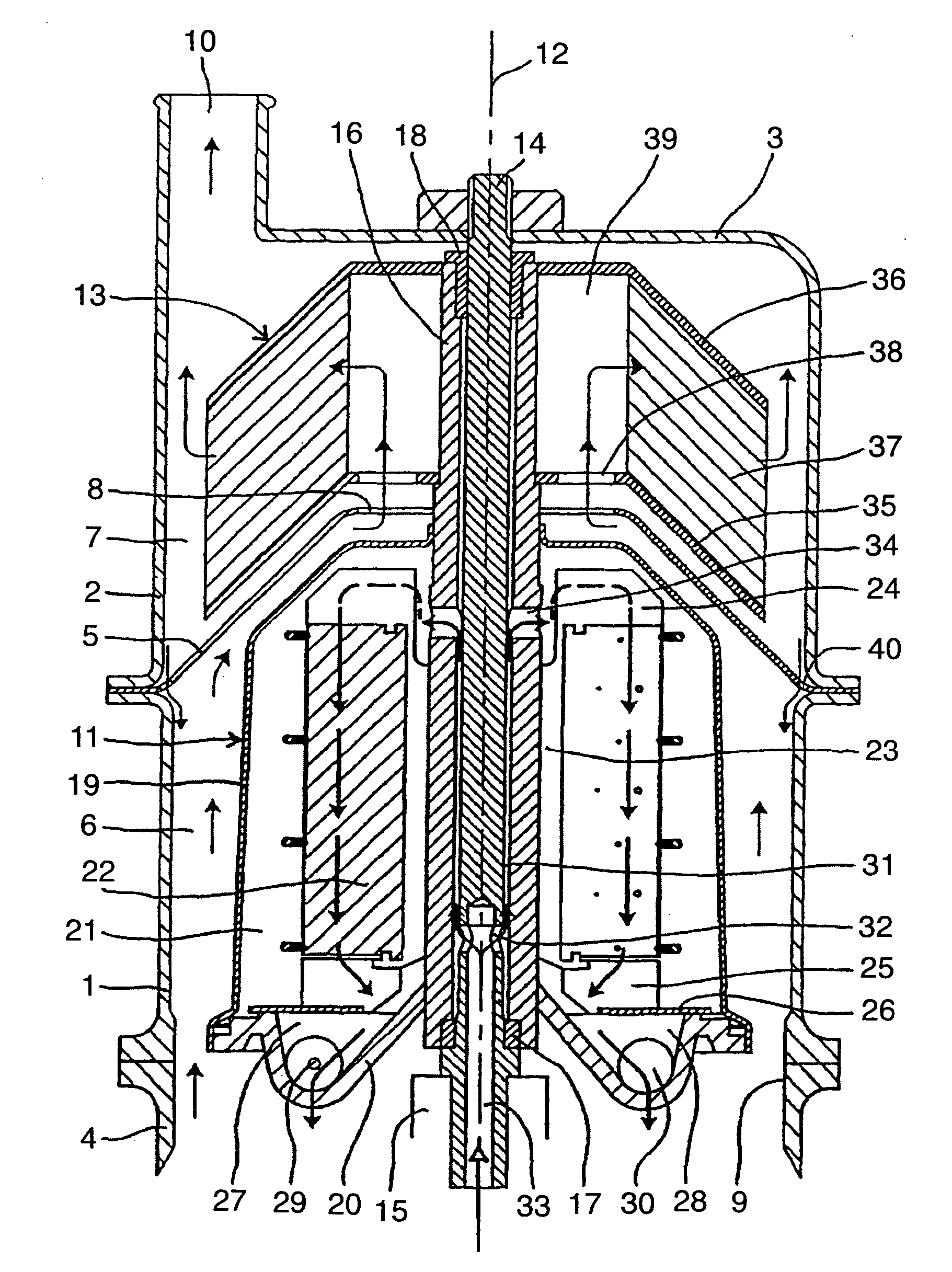
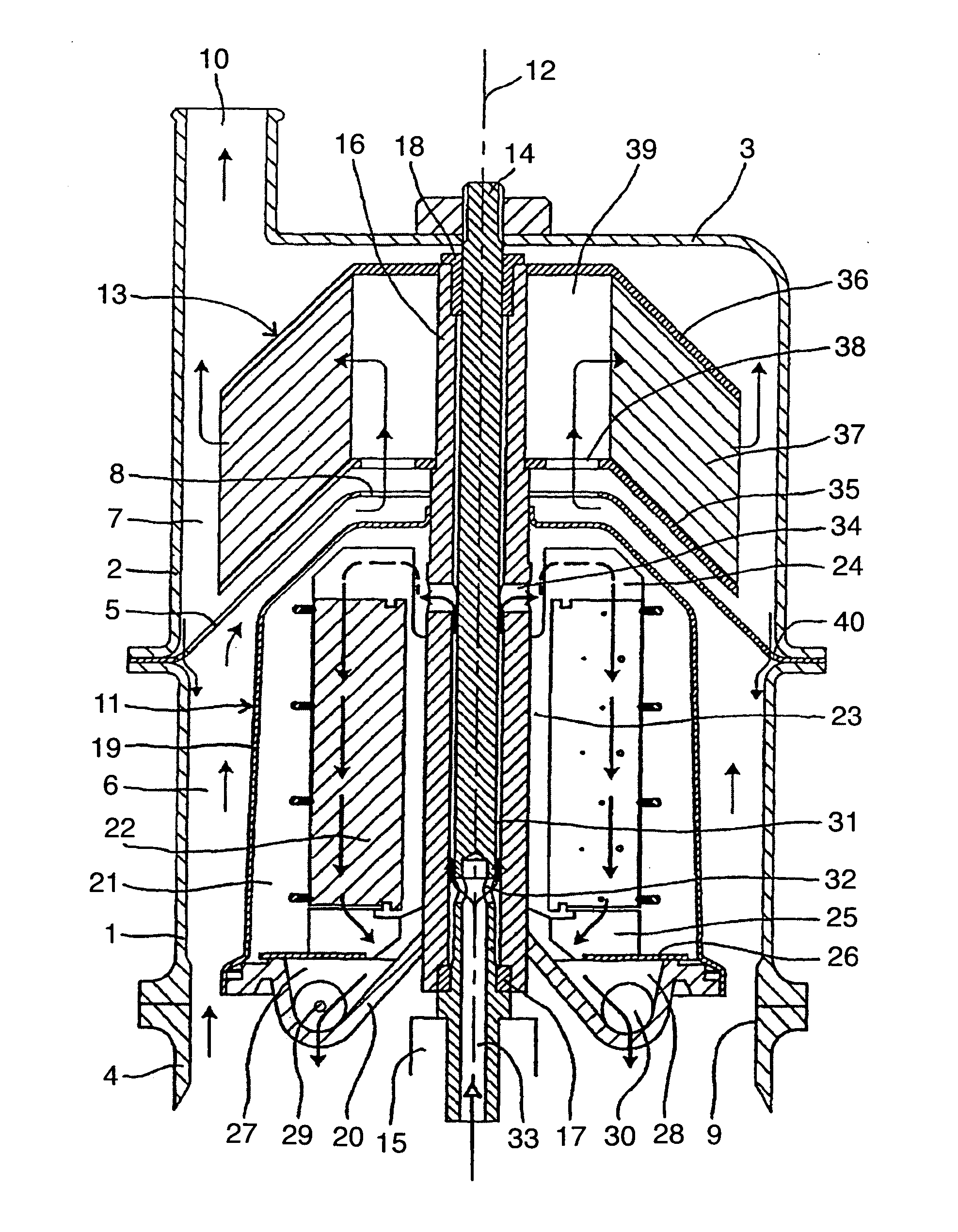
[0013] The apparatus in the drawing comprises a stationary house consisting of a housing 1, which is essentially cylindrical, and on top thereof a casing 2, which also is essentially cylindrical and which at the top has an end wall 3. The house 1, 2 rests on a foundation 4.

[0014] A frusto-conical partition 5 is fixedly arranged between the housing I and the casing 2 and divides the interior of the house into a lower chamber 6 and an upper chamber 7. The partition 5 has a central through opening 8. Gas to be cleaned may be conducted into the lower chamber 6 through an opening 9 in the foundation 4, and cleaned gas may leave the upper chamber 7 through an outlet opening 10 in the end wall 3 of the casing 2.

[0015] A centrifugal rotor 11 for cleaning of said liquid is arranged in the lower chamber 6 and is rotatable around a vertical axis 12. The centrifugal rotor 11 supports, on its upper side, a gas cleaning device 13 for cleaning of said gas. The gas cleaning device is situated in ...


PUM


Abstract

In an apparatus for simultaneous cleaning of a liquid and a gas a centrifugal rotor for cleaning of the liquid is connected with a device for cleaning of the gas. The centrifugal rotor is contained in a stationary housing, and this housing delimits a supply passage for gas to be cleaned and on its way to the cleaning device. The gas cleaning device comprises a stack of conical separation discs surrounding a gas inlet chamber and surrounded by a receiving chamber that is delimited by a surrounding stationary casing.

Description

CROSS-REFERENCE TO RELATED APPLICATIONS [0001] This application is entitled to the benefit of and incorporates by reference essential subject matter disclosed in International Application No. PCT / SE02 / 02401 filed on Dec. 19, 2002 and Swedish Patent Application No. 0200204-6 filed on Jan. 25, 2002.FIELD OF THE INVENTION [0002] The present invention relates to an apparatus for the simultaneous cleaning of a liquid from first particles suspended therein and a gas from second particles suspended therein, in which apparatus a centrifugal rotor is rotatable about a rotational axis and arranged for through flow and cleaning of said liquid, a driving device is arranged for rotation of the centrifugal rotor about said rotational axis, a gas cleaning device is connected with the centrifugal rotor for rotation together therewith and is arranged for through flow and cleaning of said gas, a stationary housing surrounds the centrifugal rotor and delimits a passage for conducting said gay to a gas...

Claims


Application Information

Patent Timeline
IPC IPC(8): B01D45/12F01M13/04B01D45/14B04B1/08B04B5/00B04B5/08B04B5/10B04B5/12
CPCB01D45/14B04B1/08B04B5/005B04B5/08Y10S55/19B04B5/12B04B2005/125F01M2013/0422B04B5/10B04B1/00B04B1/04
Inventor FRANZEN, PETERLAGERSTEDT, TORGNY
Owner ALFA LAVAL CORP AB
Why Eureka
Try Eureka