Metal sheet punch device

Inactive Publication Date: 2005-09-15
PRICE JOHN +1
View PDF6 Cites 4 Cited by
  • Summary
  • Abstract
  • Description
  • Claims
  • Application Information

AI Technical Summary

Benefits of technology

[0015] The metal sheet punch device as thus described is far superior to those devices found in the prior art. Specifically, the ability of the present device to perform simultaneous multiple punches which are accurately aligned with the underlying roof frame greatly decreases the amount of time needed to align and lay out the punched indentations required when using the methods of the prior art, such as chalk lining or the like. Furthermore, because the present invention, when outfitted with coiled springs, is independent of any power source, it is much easier and safer for a roof installer to use than many other electrical or pneumatic devices used in construction. Also, because of the forward and rearward alignment devices mounted on the long

Problems solved by technology

Specifically, the ability of the present device to perform simultaneous multiple punches which are accurately aligned with the underlying roof frame greatly decr

Method used


Image

  • Metal sheet punch device
  • Metal sheet punch device
  • Metal sheet punch device

Examples


Example

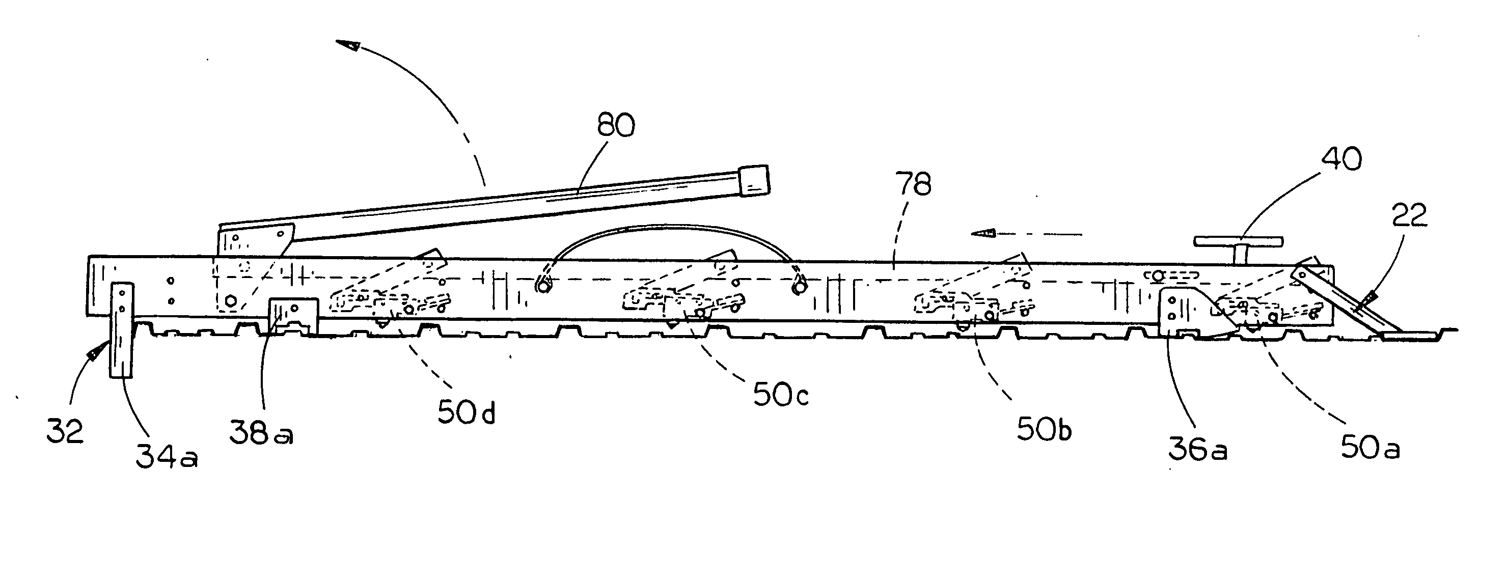
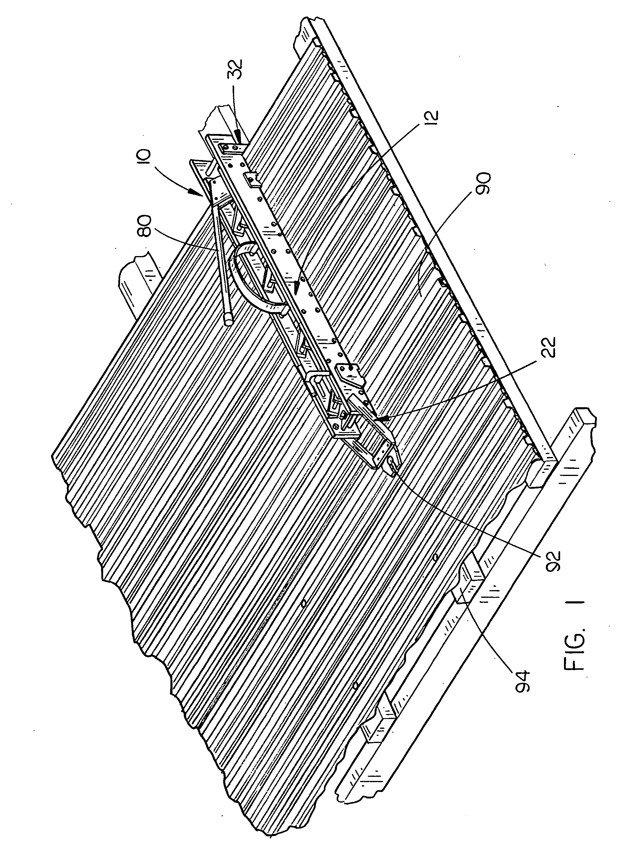
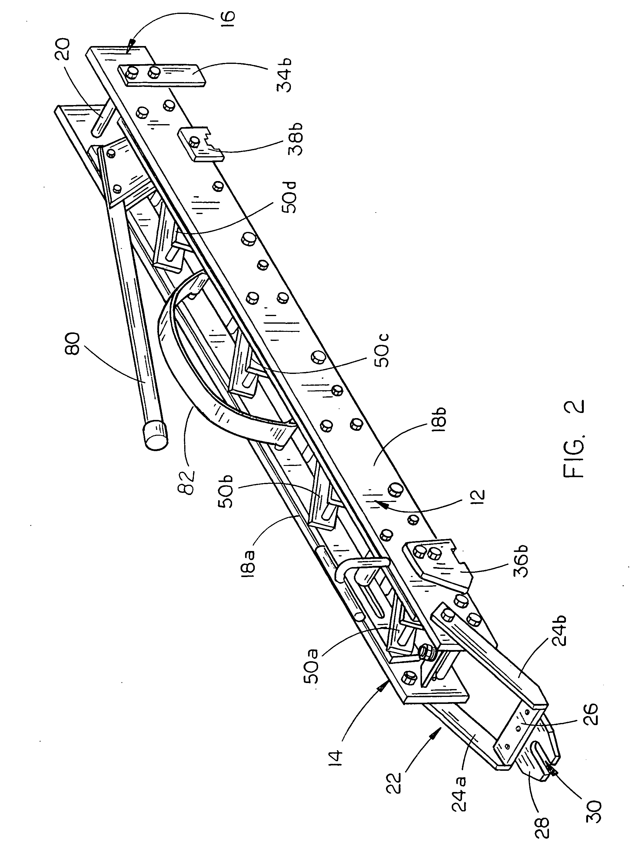
[0024] The metal sheet punch device 10 of the present invention is shown best in FIGS. 1-4 as including a longitudinally extended frame 12 having a forward end 14 and rearward end 16 and a plurality of metal punch devices 50a, 50b, 50c, and 50d which are movably mounted on the frame 12. In the preferred embodiment, the longitudinally extended frame 12 is constructed as including a pair of generally parallel frame plates 18a and 18b which are constructed of a durable material such as metal, aluminum or hardened plastic and would have a length of approximately 36 to 60 inches, a vertical height of approximately 1 to 6 inches, and would be spaced from one another approximately 1 to 6 inches, the frame plates 18a and 18b being supported apart from and connected to one another by a plurality of spacer rods 20. It is further preferred that each of the elements of the present invention be constructed of rigid and durable materials, and therefore it is expected that the metal sheet punch de...


PUM


Abstract

A metal sheet punch device for metal sheets which includes a longitudinally extended frame having forward and rearward ends and alignment devices for aligning the frame on a metal sheet. At least two metal punch devices are mounted on the frame, each including a metal punch support structure movably mounted on the frame and a metal punch having a pointed lower end, the metal punch mounted on the underside of the metal punch support arm structure. A support structure drive device such as a coiled spring is operatively connected to the metal punch support structure to rapidly move the metal punch support structure between a retracted position and an extended position and a trigger device is operatively connected to the metal punch devices to trigger each of them to drive the metal punch into the metal sheet to form at least two securement screw indentations therein.

Description

BACKGROUND OF THE INVENTION [0001] 1. Technical Field [0002] The present invention relates to punch devices and, more particularly, to a metal sheet punch device having a longitudinally extended frame having forward and rearward ends, an alignment device mounted on the frame for aligning the frame on a metal roof, at least two metal punch devices mounted on the frame, each device including a metal punch support arm structure movably mounted on the frame, a generally pointed metal punch mounted on the underside of the metal punch support arm structure, and a support arm structure drive device mounted on the frame which is operatively connected to the metal punch support arm structure to move the metal punch support arm structure between a retracted position and an extended position, and a trigger device operatively connected to each of the metal punch devices to trigger the metal punch devices to punch securement screw indentations in the metal roof. [0003] 2. Description of the Prio...

Claims


Application Information

Patent Timeline
IPC IPC(8): B21J13/00
CPCB21D22/04Y10T29/53709E04D15/04Y10T83/4717Y10T83/4734Y10T83/8851
Inventor PRICE, JOHNSCHAFER, LEIGHTON
Owner PRICE JOHN
Why Eureka
Try Eureka