Silicon integrated photonic optical parametric amplifier oscillator and wavelength converter

Active Publication Date: 2009-03-05
SHARPING JAY DR +4
View PDF7 Cites 7 Cited by
  • Summary
  • Abstract
  • Description
  • Claims
  • Application Information

AI Technical Summary

Benefits of technology

[0008]In some embodiments, the systems and methods disclose the waveguide adjusting, in response to the anomalous group velocity dispersion, the amo

Problems solved by technology

Such effects are sometimes induced by the natural material characteristics which may create technical difficulties in optical transmission systems.
In telecommunications, where optical information is often transmitted via optical fibers, degradation in optical signal, such as pulse spreading or distortion, are often attributed to the dispersions created by the medium.
In addition to the material dispersion, waveguide dispersion further degrades the signal due to the signal spreading caused by the geometries and the sizes of waveguides.
Furthermore, as the optical signal is spread due to the dispersion, the amplitude of the optical signal is also degraded.
All these effects combined often define limitations to the efficiency of many transmission systems.

Method used


Image

  • Silicon integrated photonic optical parametric amplifier oscillator and wavelength converter
  • Silicon integrated photonic optical parametric amplifier oscillator and wavelength converter
  • Silicon integrated photonic optical parametric amplifier oscillator and wavelength converter

Examples


Embodiment Construction

[0029]For purposes of reading the description of the various embodiments of the present invention below, the following descriptions of the sections of the specification and their respective contents may be helpful:[0030]Section A describes the environment and the system components for practicing embodiments of the present invention;[0031]Section B describes embodiments for methods for phase adjustment;[0032]Section C describes embodiments for methods of optical signal intensity or power adjustment by the photonic apparatus; and[0033]Section D describes embodiments for methods of wavelength adjustment by the photonic apparatus.

A. The System Components and Environment

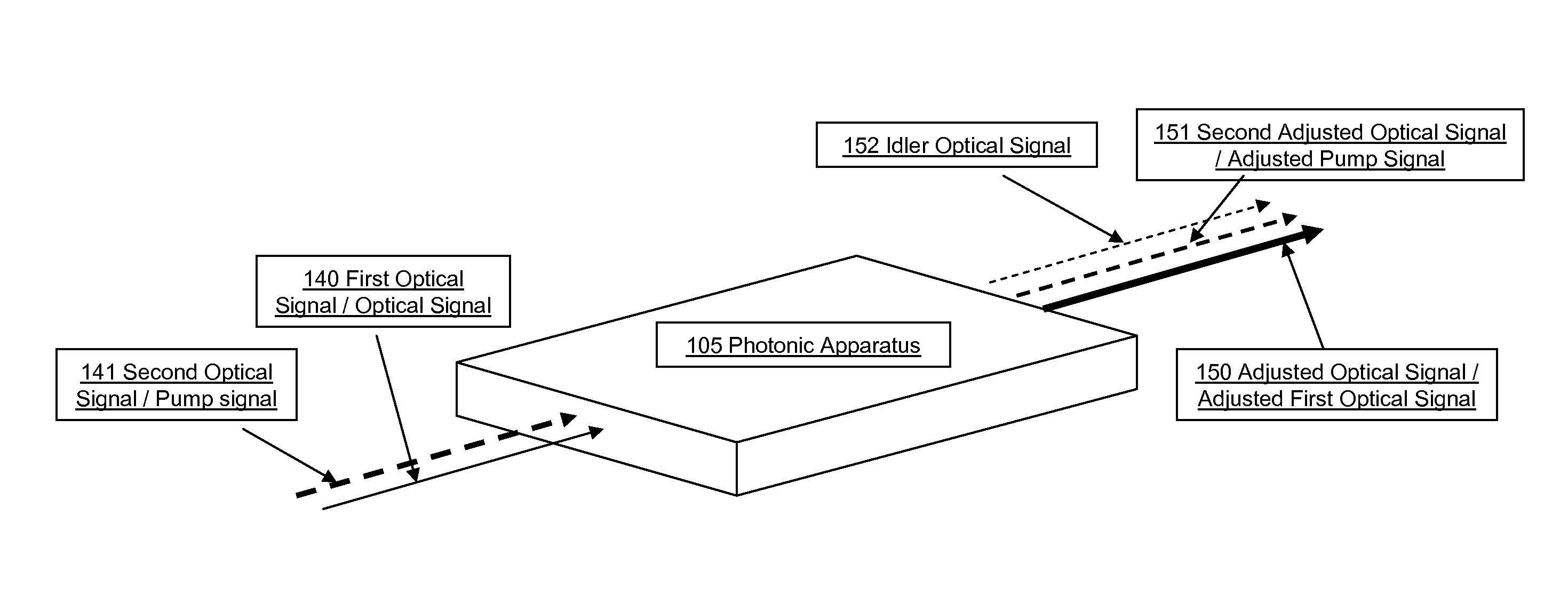
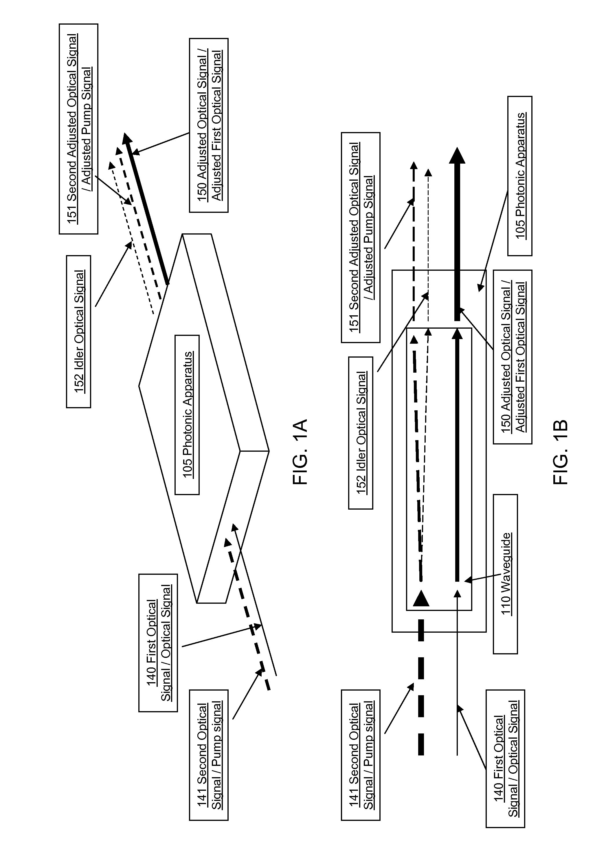
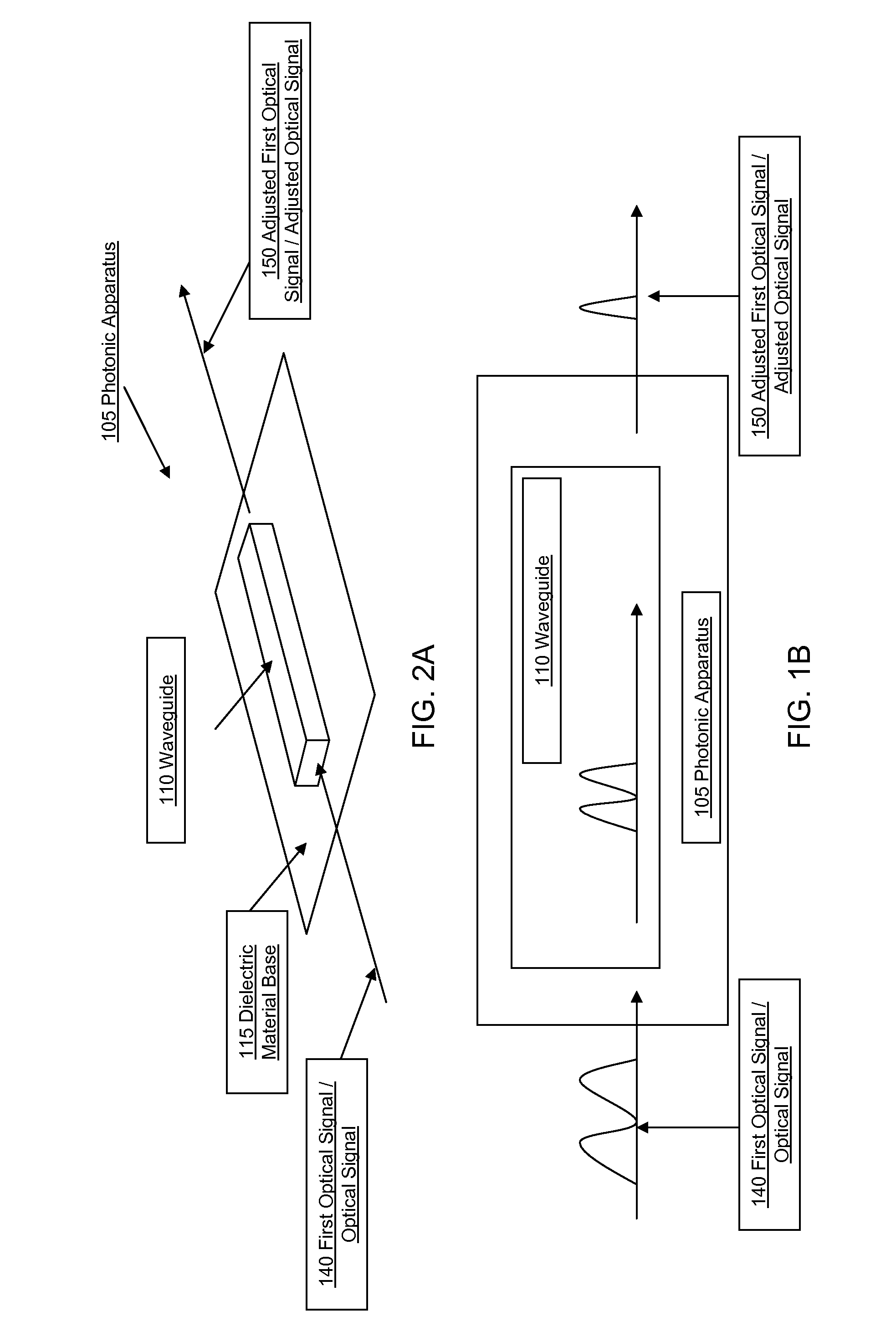
[0034]Prior to discussing specific embodiments of systems and methods relating to the present invention, it may be helpful to discuss the general environment in which the present invention may be used. One such environment may include an optical communication system used in an industry such as, for example, the telecommun...


PUM


Abstract

The present invention is directed towards systems and methods for adjusting intensity, wavelength and higher and lower frequency components of an optical signal. Photonic apparatus receives a first and a second optical signal. A waveguide provides an anomalous group velocity dispersion the first optical signal or the second optical signal and adjusts intensity or wavelength of the first optical signal or the second optical signal, in response to the anomalous group velocity dispersion. In some embodiments photonic apparatus receives an optical signal comprising a lower frequency component received an amount of time prior to a higher frequency component of the optical signal. A waveguide provides an anomalous group velocity dispersion for the optical signal and adjusts the amount of time between the higher frequency component and the lower frequency component in response to the anomalous group velocity dispersion.

Description

RELATED APPLICATIONS[0001]This application claims priority to and the benefit of U.S. Provisional Patent Application No. 60 / 908,002, entitled “Silicon Integrated Photonic Optical Parametric Amplifier, Oscillator and Wavelength Converter”, and filed on Mar. 26, 2007, which is incorporated herein by reference in its entirety.GOVERNMENT SUPPORT[0002]This invention was made with Government support under DARPA Grant No. N000014-05-1-053 and under NSF / Center for Nanoscale Systems Grant No. NSF-117770. The United States Government has certain rights in the invention.FIELD OF THE INVENTION[0003]The present application generally relates to optical signal processing and amplification. More specifically, the present application relates to systems, methods and apparatuses for wavelength shifting, phase matching and amplification of optical signals performed by a semiconductor photonic device.BACKGROUND OF THE INVENTION[0004]When an optical wave, emitted from a monochromatic light source such as...

Claims


Application Information

Patent Timeline
IPC IPC(8): G02F1/295H04B10/12
CPCG02F1/39H04B10/291H04B10/25133
Inventor FOSTER, MARKGAETA, ALEXANDERLIPSON, MICHALSHARPING, JAYTURNER, AMY
Owner SHARPING JAY DR
Why Eureka
Try Eureka