Apparatus for the preparation of film

a technology of apparatus and film, applied in the direction of polycrystalline material growth, crystal growth process, chemically reactive gas, etc., can solve the problem that the decisive means of solving problems cannot be found in the substratum, and achieve uniform plane distribution

Active Publication Date: 2005-09-15
ULVAC INC
View PDF7 Cites 35 Cited by
  • Summary
  • Abstract
  • Description
  • Claims
  • Application Information

AI Technical Summary

Benefits of technology

[0005] Accordingly, it is an object of the present invention to solve the foregoing problems associated with the conventional techniques for preparing a thin film according to the CVD technique such as the MOCVD technique and more specifically to provide an apparatus for producing a thin film, which can easily ensure the uniform plane distribution of, for instance, the thickness, quality and composition of a film formed on the surface of a substrate or a wafer.

Problems solved by technology

The foregoing various kinds of conventional techniques proposed for the preparation of a thin film having uniform distribution of quality and thickness of a film thus formed on a substrate cannot be decisive means for solving the problems concerning the formation of a thin film, on a substrate, having, for instance, good uniformity in the quality and distribution of thickness, because of, for instance, the complicated structure of the currently used MOCVD apparatus and the difficulty in the formation of a uniform gas mixture.

Method used


Image

  • Apparatus for the preparation of film
  • Apparatus for the preparation of film
  • Apparatus for the preparation of film

Examples


example 1

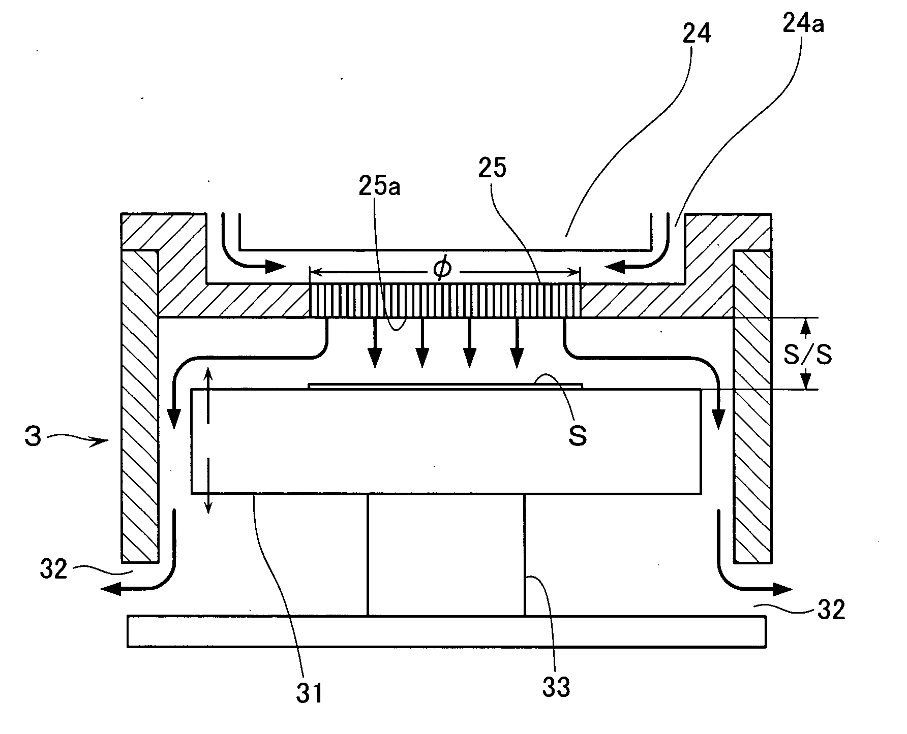
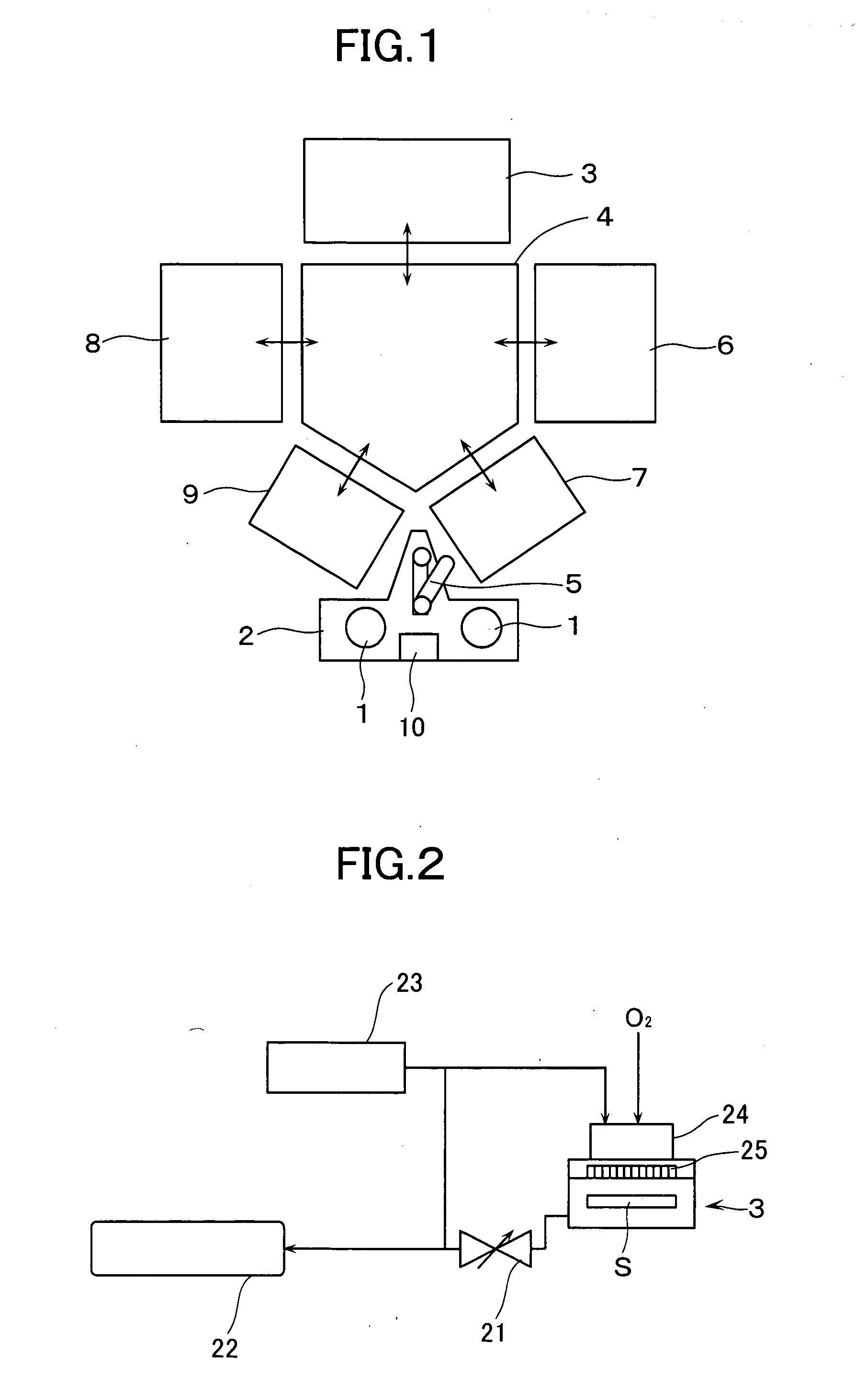
[0058] In this Example, a ferroelectric PZT thin film was prepared using either of the thin film-forming apparatuses as shown in FIGS. 1 to 3 in which a thin film is formed according to the MOCVD technique.

[0059] In the apparatuses as shown in FIGS. 1 to 3, the following variables were set at the levels specified below: [0060] Diameter of Shower Head 25: 150 to 250 mm; [0061] Number of Holes Formed through Shower Head 25: 3000 holes / Φ250; [0062] Conductance of Shower Head 25 per Unit Area (1 m2): 7.3 m3 / s; and [0063] Distance Between Shower Head 25 and Substrate: 15 to 45 mm.

Such a shower head 25 used herein was one having a uniform hole density as shown in FIG. 5(a).

[0064] In addition, the following film-forming conditions were used herein: [0065] Flow Rate of Gases: [0066] Reactive Gas (O2): 2500 sccm; [0067] Carrier Gas (N2): 300 sccm; [0068] Flow Rate of Liquid Raw Materials: [0069] 0.3M-Pb(DPM)2 / THF: 0.3 mL / min, [0070] 0.3M-Zr(DMHD)4 / THF: 0.2 mL / min and [0071] 0.3M-Ti(i-PrO...

example 2

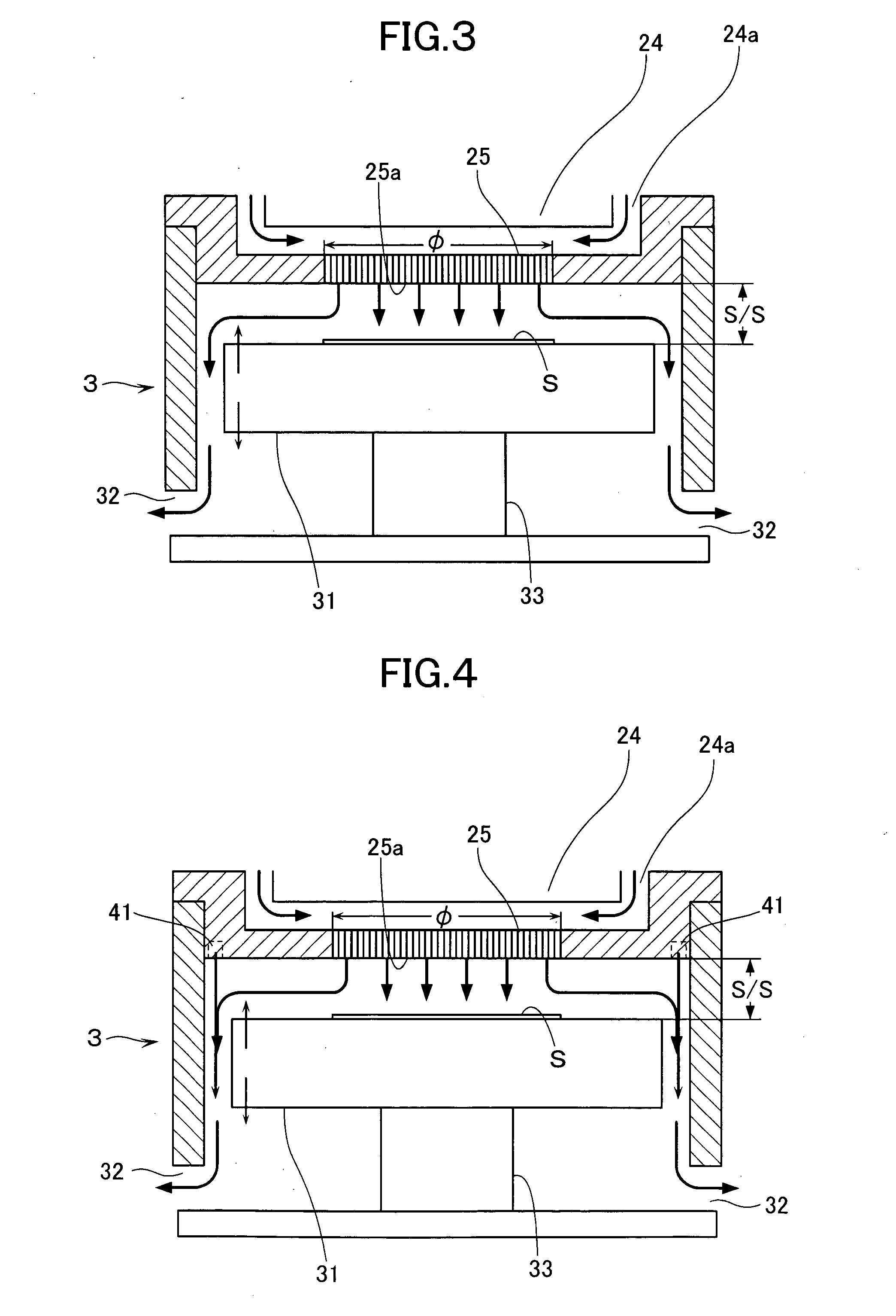
[0092] The shower head 25 used in Example 1 was one whose gas-injection holes 25a were uniformly distributed throughout the cross-section of the shower head (see FIG. 5(a)), while the same procedures used in Example 1 were repeated except for using shower heads such as those depicted on FIGS. 5(b) to 5(e) in which the hole density thereof was changed or the hole density thereof had a distribution depending on the flow rates of the gas mixture and the exhaustion speed of the pump. As a result, it was found that the same results observed in Example 1 were obtained.

example 3

[0093] The same procedures used in Example 1 were repeated except that a film-forming chamber provided with a gas ring 41 as shown in FIG. 4 was substituted for the film-forming chamber 3 used in Example 1 and that an inert gas such as N2 or Ar was passed through the film-forming chamber in such a manner that the inert gas flew along the side wall of the film-forming chamber. As a result, it was found that the gas mixture flew as a more rectified flow to thus give a more preferred film thickness distribution.


PUM

PropertyMeasurementUnit
pressureaaaaaaaaaa
pressureaaaaaaaaaa
pressureaaaaaaaaaa

Abstract

A thin film-forming apparatus, for ensuring uniform plane distribution of properties of a film formed on a substrate surface, has a gas-supply port 24a supplying a gas mixture from a gas-mixing chamber 24 to a shower head 25. The port is arranged at the peripheral portion on the bottom face of the gas-mixing chamber so that the gas mixture flows from the upper peripheral region of the head towards the center thereof. An exhaust port 32 discharging the exhaust gas generated in the film-forming chamber 3 is arranged at a position lower than the level of a stage 31 during film-formation directing the exhaust gas towards the side wall of the chamber 3 and discharging the exhaust gas through the exhaust port. The stage 31 is designed to move freely up and down to adjust the distance between the shower head 25 and substrate S.

Description

BACKGROUND OF THE INVENTION [0001] The present invention relates to an apparatus for the preparation of a thin film and, in particular, to an apparatus for the manufacture of a thin film, which can improve the distributions of, for instance, thickness, quality and composition of the resulting thin film on the surface of a wafer (or a substrate) when a film is formed according to the CVD technique such as the MOCVD technique. [0002] Up to now, there have been proposed various kinds of techniques such as that for uniformly admixing a raw gas and a reactive gas; that for appropriately rotating a wafer to be processed during the formation of a film; and that for uniformly injecting gases onto the wafer through a shower head of a film-forming chamber, as means for improving the plane uniformity in the distributions of, for instance, thickness, quality and composition of the resulting thin film on the surface of a wafer, when a thin film is prepared according to the CVD technique, for ins...

Claims


Application Information

Patent Timeline
Patent Type & Authority Applications(United States)
IPC IPC(8): C23C16/40C23C16/44C23C16/455C30B25/02C30B25/14H01L21/205
CPCC23C16/409C23C16/45512C23C16/45519C23C16/45565C23C16/45589C30B25/14C30B25/02C30B29/60H01L21/205
Inventor MASUDA, TAKESHIKAJINUMA, MASAHIKOYAMADA, TAKAKAZUUCHIDA, HIROTOUEMATSU, MASAKISUU, KOUKOU
Owner ULVAC INC
Why Eureka
Try Eureka