
High flow nozzle system for flow control in bladder surge tanks

a technology of surge tank and nozzle system, which is applied in the direction of pipe/joint/fitting, mechanical equipment, pipe elements, etc., can solve the problems of affecting the flow of liquid through the screen, the shape of the bladder during gas precharge or fluid discharge is not totally controllable, and the damage to the bladder. , to achieve the effect of reducing or eliminating the possibility, quick and uniform entry, and reducing damage to the bladder

Inactive Publication Date: 2005-09-15
YOUNG WINSTON B
View PDF23 Cites 0 Cited by
  • Summary
  • Abstract
  • Description
  • Claims
  • Application Information

AI Technical Summary

Benefits of technology

[0009] High flow nozzle systems of this invention are provided for use with bladder surge tanks for the purpose of overcoming the aforementioned bladder blockage and bladder damage problem in the prior art bladder surge tanks. The nozzle systems of this invention comprise a uniquely designed nozzle member that is configured to cover the surge tank's fluid inlet / outlet opening. The nozzle member is designed to allow fluid to quickly and uniformly enter and exit the tank while at the same time reducing or eliminating the possibility of having the bladder block the tank's inlet / outlet fluid opening during fluid discharge.
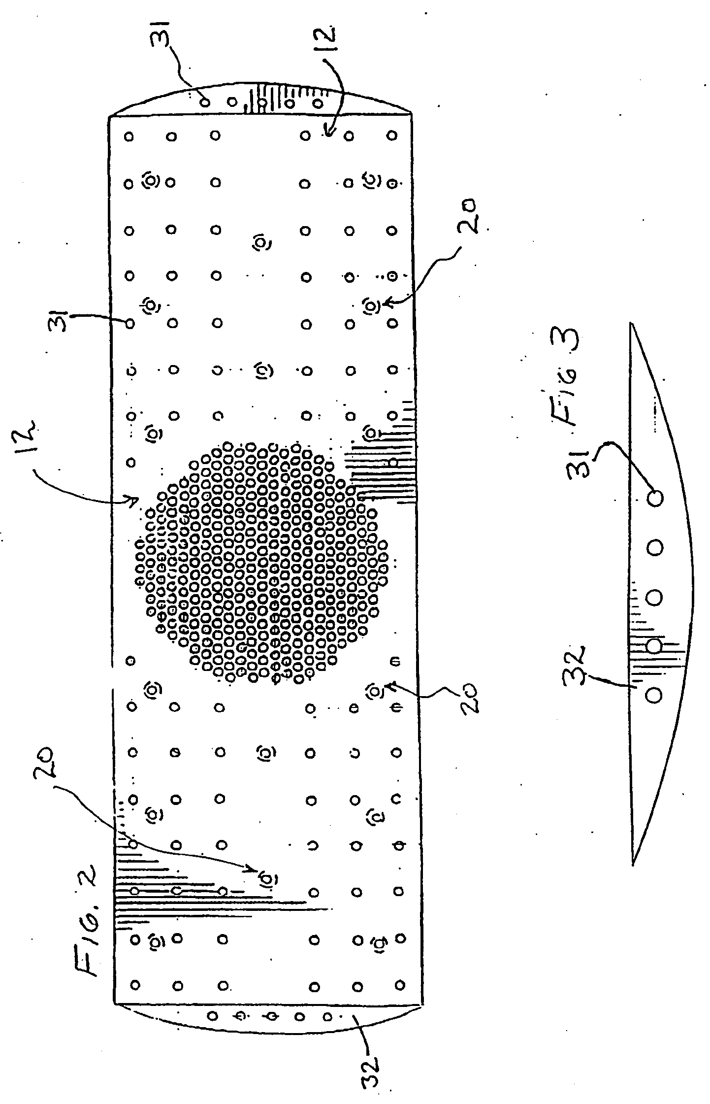
[0010] The inventive nozzle member is provided in the form of a diffusor having multiple perforations, which act to disperse the fluid as it enters the tank, thereby redirecting the force of the incoming fluid and reducing damage to the bladder. Two embodiments of this inventive nozzle system include a horizontal nozzle member for use in a horizontal bladder surge tank, and a vertical nozzle member for use in a vertical bladder surge tank. The nozzle member can be integral with the tank's fluid inlet / outlet port, i.e., be provided as part of the inlet / outlet port itself, or can be non-integral with the inlet / outlet port, i.e., be separate from the inlet / outlet port.
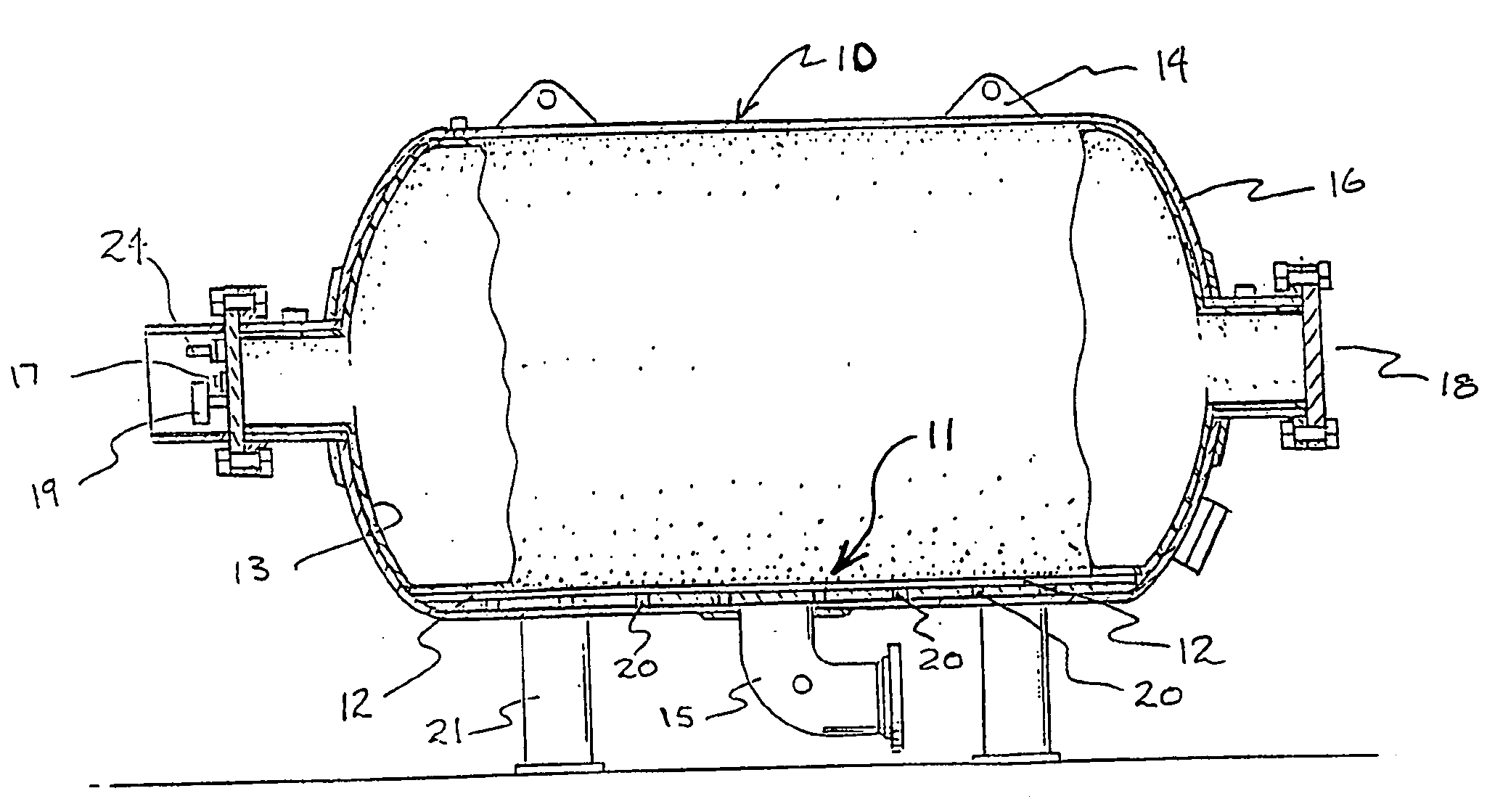
[0011] In the case of applications within both the vertical and horizontal surge tanks, the inventive nozzle member is located between the tank's bladder and the tank's fluid inlet / outlet opening. The nozzle member has numerous perforations or openings therethrough that are arranged in a unique pattern. The perforation design also allows fluid to rapidly and uniformly enter or exit the surge tank, thereby eliminating unwanted pressure transients. The location, size, pattern, and number of openings through the nozzle member are mathematically determined to greatly reduce, if not eliminate altogether, the possibility of having the bladder collapse and block the tank's inlet / outlet opening before all of the fluid has been discharged. The openings also operate to disperse and redirect the flow of fluid entering the bladder surge tank, such that the force exerted by the incoming fluid is not directed towards a single portion of the bladder.
[0012] High flow nozzle systems of this invention are suitable for use in bladder tanks used in virtually every industry, including waste water and sewage systems, fuel-loading systems, petrochemical and chemical systems, desalination, and fire protection systems. Horizontal and vertical bladder surge tanks, fabricated with the nozzle system of this invention, provide a means for redirecting and more uniformly distributing the fluid entering the tank, thereby reducing the possibility of damage to the bladder caused by the force of the fluid during a sudden inflow. Further, upon a sudden dispensement of fluid from the tank, the inventive nozzle system virtually eliminates the possibility of having the bladder block the tank's inlet / outlet opening before all of the fluid has been discharged.

Problems solved by technology

Pressure transients can be either positive or negative and are potentially destructive and may result in damage to piping, pumps, instruments, fittings, or other system components.
Regardless of the application, the shape of the bladder during gas precharge or fluid discharge is not totally controllable.
Unfortunately, such a screen actually impedes the liquid flow and is not totally effective in preventing the bladder from blocking the tank's fluid inlet / outlet opening during fluid discharge.
Such a column of fluid and its associated force is directed towards that portion of the bladder directly above the tank's inlet / outlet opening and can cause damage to the bladder.

Method used


Image

  • High flow nozzle system for flow control in bladder surge tanks
  • High flow nozzle system for flow control in bladder surge tanks
  • High flow nozzle system for flow control in bladder surge tanks

Examples


Embodiment Construction

[0023] In accordance with the present invention, there is provided improved bladder surge tanks comprising high flow nozzle systems suitable for use in various systems such as fire protection systems, waste water and sewage systems, fuel loading systems, desalination systems, and chemical and petro-chemical facilities. In particular, bladder surge tanks comprising high flow nozzle systems of this invention have specific application as deluge tanks, where the immediate discharge of liquid is required, in for example fire retardation.

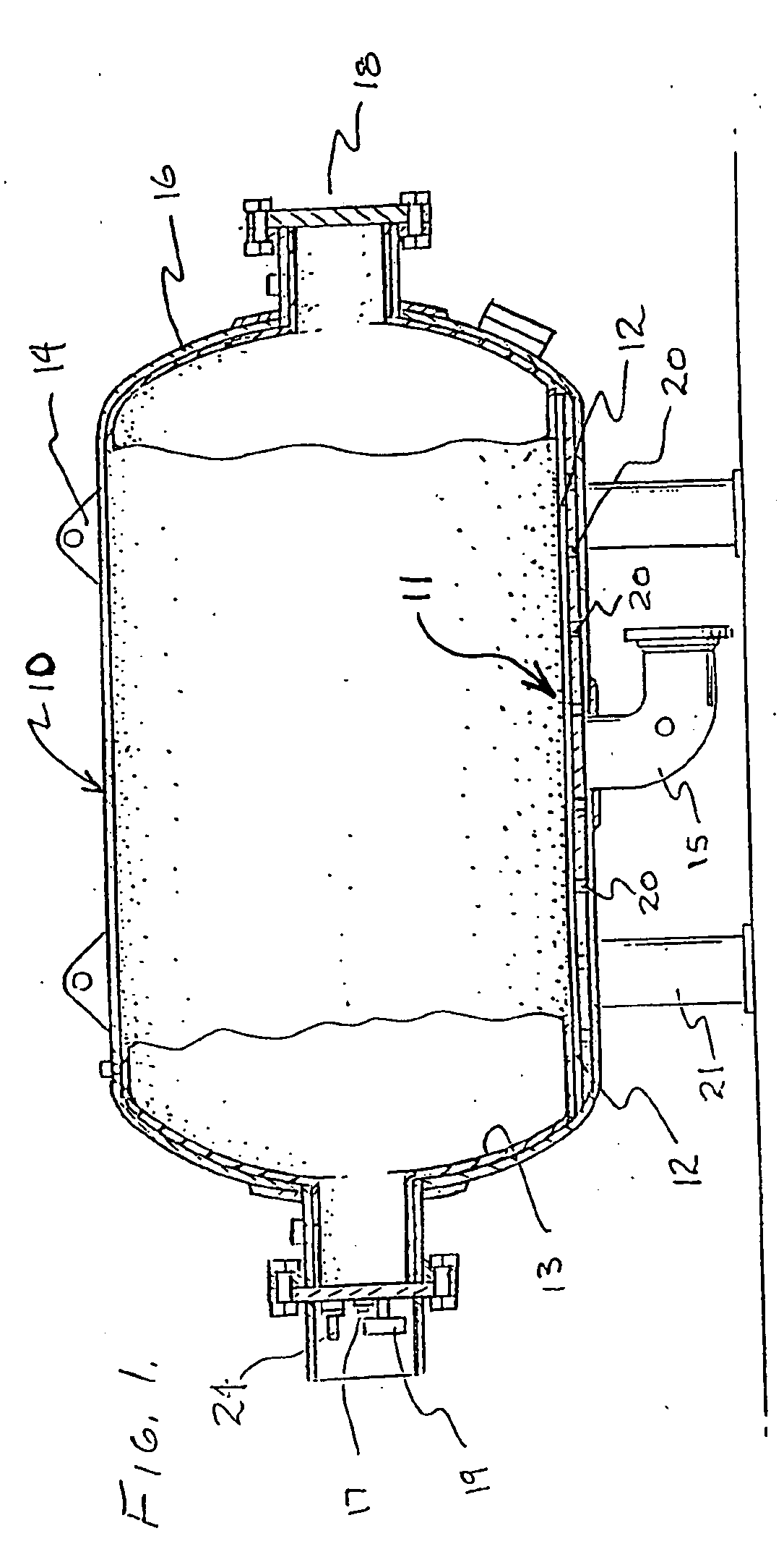
[0024]FIG. 1 illustrates a horizontal bladder surge tank 10 comprising a high flow nozzle system 11 of this invention. The horizontal bladder surge tank 10 is a pressure vessel which contains a bladder 13, a liquid port or a fluid inlet / outlet port 15, and a nozzle system 11 positioned within the tank adjacent a terminal end of the inlet / outlet port 15. The horizontal bladder surge tank 10 comprises a body 16 having a bladder access opening 18 disposed t...


PUM


Abstract

A bladder surge tank includes a liquid port, and a bladder disposed therein for providing a surge absorbing interface between liquid and pressurized gas within the tank. The bladder surge tank can be horizontally or vertically oriented. In a horizontal embodiment, the surge tank includes a nozzle system disposed horizontally therein that is separate from the liquid port and that is integrally joined to the interior wall. Such nozzle system includes a nozzle member positioned between the liquid port and the bladder, and comprises a plurality of perforations disposed therethrough. In a vertical embodiment, the surge tank includes a nozzle system disposed vertically therein that is part of the liquid port and that includes a nozzle member having a plurality of perforations disposed therethrough. In both embodiment, the perforations define a total area that is greater than a total area of the liquid port, and the perforations are distributed throughout the nozzle member such that liquid entering the tank body through the liquid port is dispersed uniformly into the tank body.

Description

CROSS-REFERENCE TO RELATED APPLICATIONS [0001] This application claims the benefit of U.S. Provisional application Ser. No. 60 / 301,732, filed on Jun. 27, 2001.FIELD OF THE INVENTION [0002] The present invention relates to a surge tanks, and more specifically, bladder surge tanks having a nozzle adapted to allow liquid to uniformly enter and exit the bladder surge tank. BACKGROUND OF THE INVENTION [0003] Surge tanks are designed to control pressure surges or transients in pipelines, which are created when the flow of the fluid is abruptly changed. Pressure transients can be either positive or negative and are potentially destructive and may result in damage to piping, pumps, instruments, fittings, or other system components. [0004] Surge tanks have been used for years as a means for controlling pressure transients. Some surge tanks employ a bladder design and are well known having applications within various industries, including fire protection systems, municipal water and sewage sy...

Claims


Application Information

Patent Timeline
Patent Type & Authority Applications(United States)
IPC IPC(8): F16L55/053
CPCF16L55/053
Inventor YOUNG, WINSTON B.
Owner YOUNG WINSTON B
Learn More