
Method of making optical microstructure pattern on light guide plate, light guide plate thereof and imprinting mold

a technology of light guide plate and microstructure pattern, which is applied in the direction of optical elements, manufacturing tools, instruments, etc., can solve the problems of guide unit scratching or piercing the optical film, affecting the quality of light guide plate, so as to prevent the deterioration of the light guide plate's guiding performance and the cost of processing equipment acquisition.

Inactive Publication Date: 2012-08-02
GLOBAL LIGHTING TECHNOLOGIES INC
View PDF4 Cites 15 Cited by
  • Summary
  • Abstract
  • Description
  • Claims
  • Application Information

AI Technical Summary

Benefits of technology

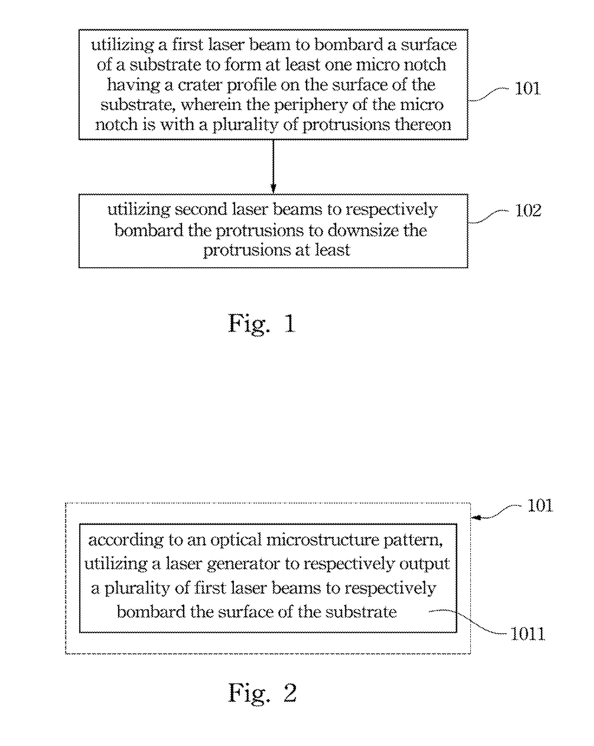
[0013]The present invention discloses a method of making an optical microstructure pattern on a light guide plate, for reducing or eliminating the possibilities of the protrusions at the periphery of a micro notch filling in the micro notch due to falling off, and the light guiding performance of the light guide plate is therefore decayed.
[0014]The present invention discloses a method of making an optical microstructure pattern on a light guide plate, for reducing or eliminating the possibilities of the light guide plate damaging optical film stacked therewith in a display device.
[0016]As what is mentioned above, the method of making an optical microstructure pattern on a light guide plate provided by the present invention does not need additional processing means to smash and eliminate the crater profile at each micro notch, so the processing cost and expenditure for acquiring the processing equipment are saved. Moreover, the light guiding performance of the light guide plate can be prevented from deterioration after being made.

Problems solved by technology

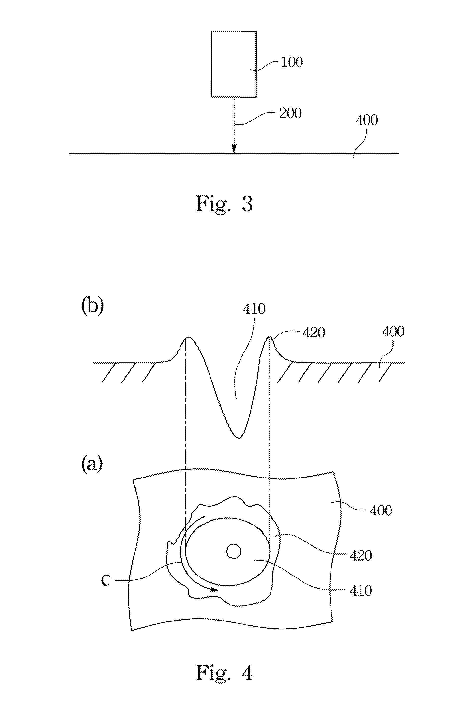
However, utilizing the laser to irradiate the surface of the substrate would inevitably generate the so called “molten slag splashing phenomenon”, thus, each micro notch may be formed with a crater profile, i.e. the periphery of the micro notch is formed with one protrusion or a plurality of protrusions.
Thus the light guiding performance of the light guide unit may be decayed.
Moreover, because of the molten slag splashing phenomenon, the protrusions may be formed with reverse-hook shapes, so when the light guide unit is installed in a display device, and stacked with other optical films, the protrusions of the light guide unit is unbeneficial for being tightly adhered with the optical films, so the light output efficiency is decreased, or the protrusions of the light guide unit may scratch or pierce the optical films.

Method used


Image

  • Method of making optical microstructure pattern on light guide plate, light guide plate thereof and imprinting mold
  • Method of making optical microstructure pattern on light guide plate, light guide plate thereof and imprinting mold
  • Method of making optical microstructure pattern on light guide plate, light guide plate thereof and imprinting mold

Examples


Embodiment Construction

[0052]In the following detailed description, for purposes of explanation, numerous specific details are set forth in order to provide a thorough understanding of the disclosed embodiments. It will be apparent, however, that one or more embodiments may be practiced without these specific details. In other instances, well-known structures and devices are schematically shown in order to simplify the drawings.

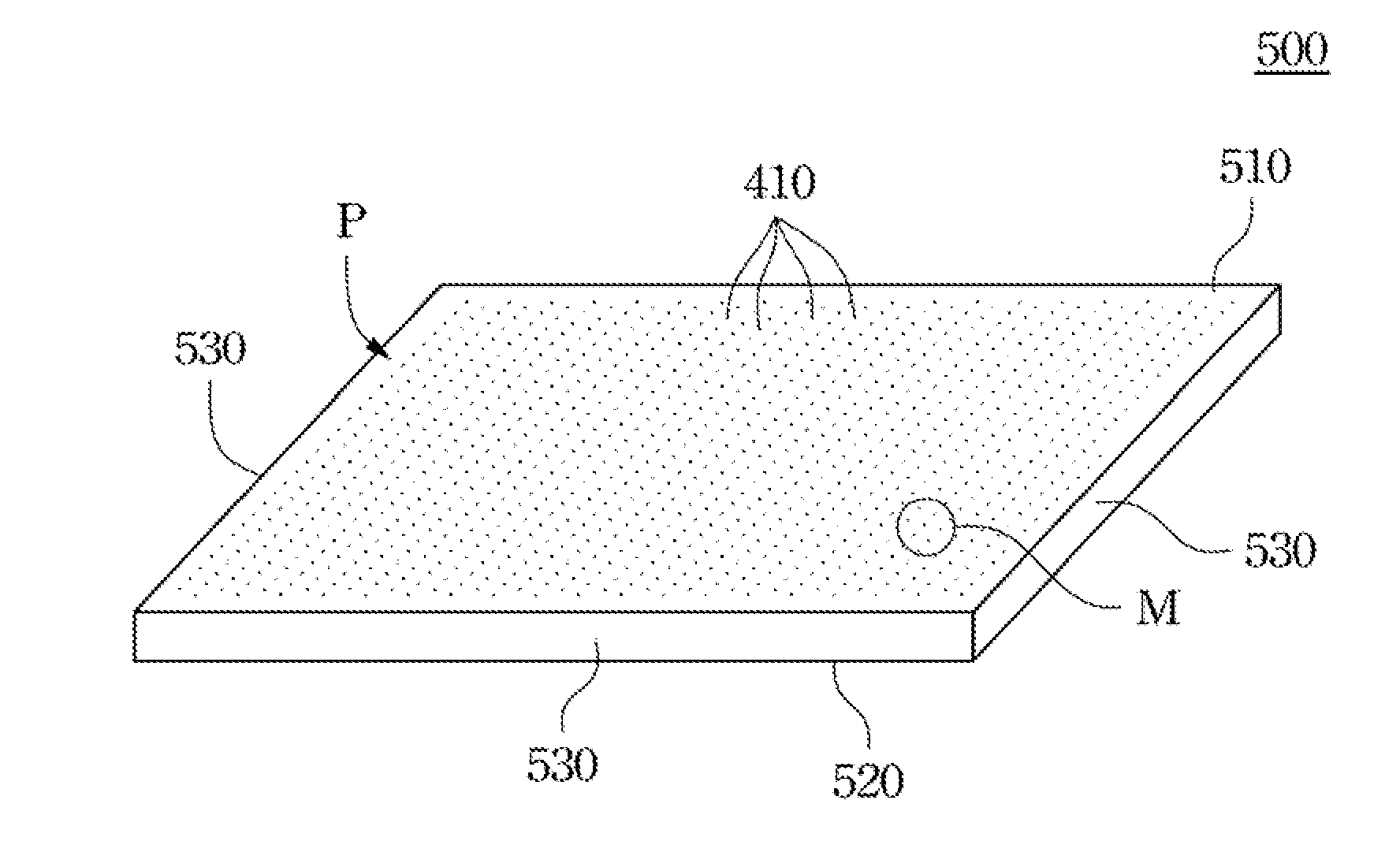
[0053]As what is mentioned above, utilizing laser beams (called laser hereinafter) to irradiate and penetrate through a surface of a substrate would inevitably generate the molten slag splashing phenomenon, thus, each micro notch may thereby formed with a crater profile, protrusions at the periphery of the crater may fall into the micro notch, and the light guiding performance of a light guide unit is therefore decayed. The present invention utilizes the laser used to form the micro notch to downsize or eliminate the crater profile at each micro notch at the same stage when the mic...


PUM

PropertyMeasurementUnit
optical microstructureaaaaaaaaaa
dimensionaaaaaaaaaa
poweraaaaaaaaaa

Abstract

The present invention discloses a method of making an optical microstructure patterns on a light guide plate, a light guide plate thereof and a imprinting mold. The method of making the optical microstructure patterns on the light guide plate includes a step of bombarding the surface of a substrate to form a micro notch thereon by laser, in which the periphery of the micro notch has as at least a protrusion, and a step of bombarding the protrusion to at least downsize the protrusion by another laser.

Description

RELATED APPLICATIONS[0001]This application claims priority to Taiwan Application Serial Number 100103673, filed Jan. 31, 2011, Taiwan Application Serial Number 100103675, filed Jan. 31, 2011 and Taiwan Application Serial Number 100103680, filed Jan. 31, 2011, which are herein incorporated by reference.BACKGROUND[0002]1. Technical Field[0003]The present invention relates to a method of making a light guide plate, more particular to a method of making an optical microstructure pattern on a light guide plate.[0004]2. Description of Related Art[0005]Conventionally, when making an optical microstructure on a surface of a light guide unit, one of the methods is to utilize laser beams (called laser hereinafter) to in sequence bombard a surface of a substrate (e.g. the light guide unit itself or an imprinting mold), such that the surface of the substrate are formed with a plurality of micro notches through being melted via the laser, so as to directly make optical microstructures on the sur...

Claims


Application Information

Patent Timeline
Patent Type & Authority Applications(United States)
IPC IPC(8): G02B6/26B23K26/38
CPCB23K26/0084B23K26/063B23K26/385G02B6/0065B29C43/021G02B6/0036B41M5/265B23K26/0622B23K26/389B23K26/355
Inventor IE, JIUN-HAU
Owner GLOBAL LIGHTING TECHNOLOGIES INC
Learn More