

Latch apparatus and method
a technology of latches and latches, applied in the field of latches, can solve the problems of failure and fatigue of the conventional linkage of power-closing latches
- Summary
- Abstract
- Description
- Claims
- Application Information
AI Technical Summary
Benefits of technology
Problems solved by technology
Method used
Image

Examples
Embodiment Construction
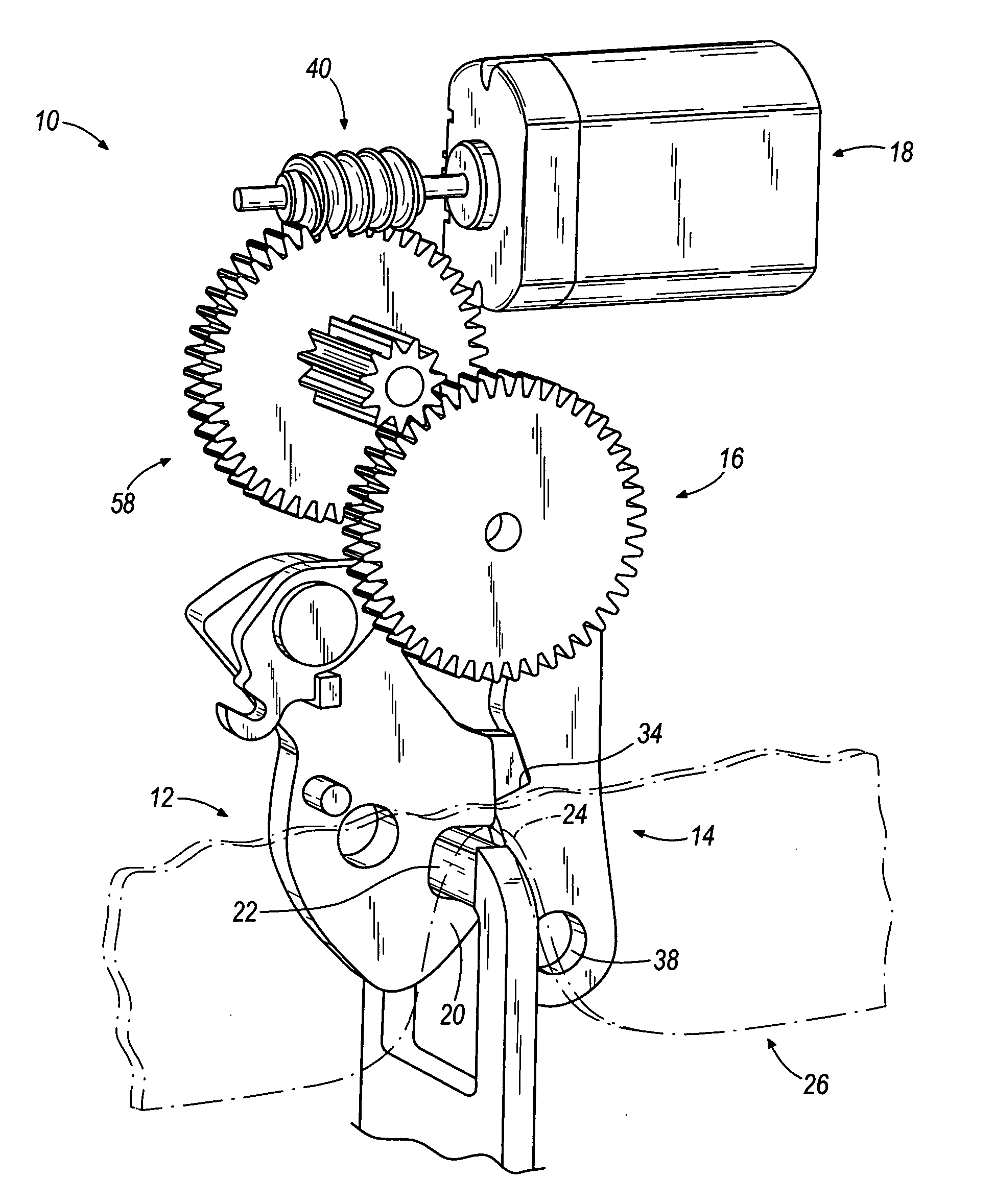
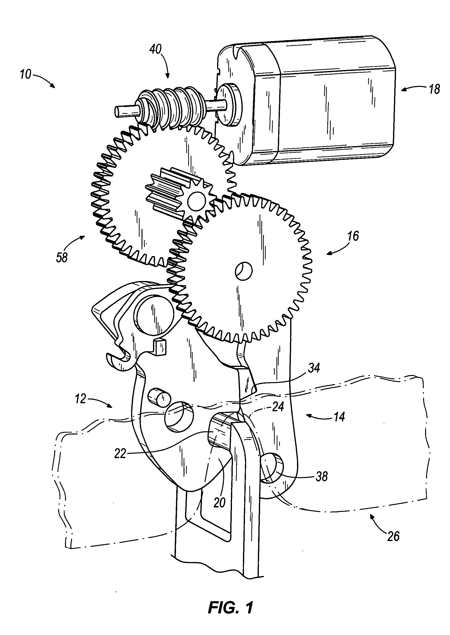
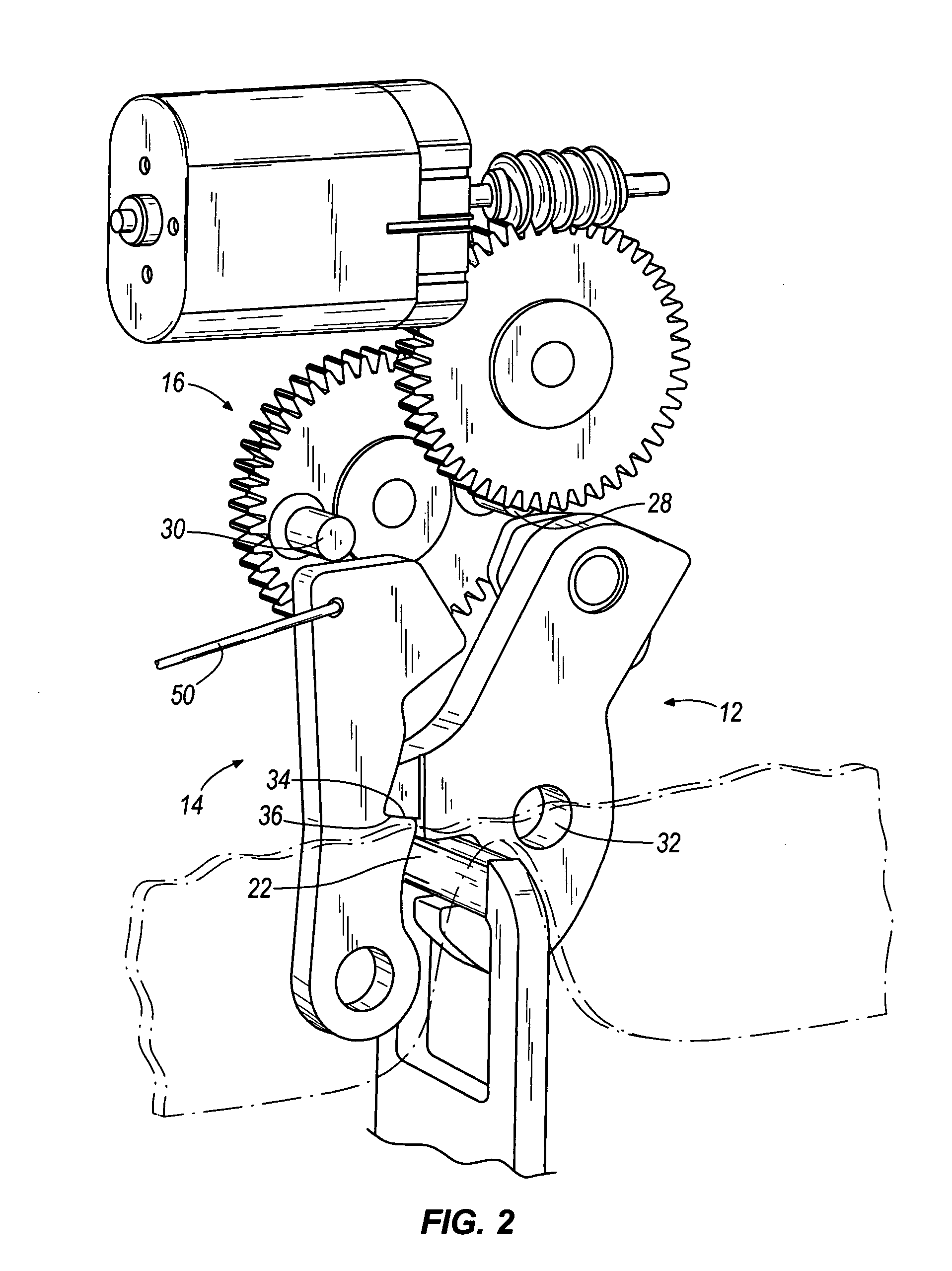
[0020] With reference to FIG. 1, a latch 10 according to an embodiment of the present invention includes a catch 12, a pawl 14, and an actuator wheel 16. The actuator wheel 16 is driven by an electric motor 18 that is coupled to the actuator wheel 16 through a worm gear arrangement including a worm gear 40 and an intermediate gear wheel 58. In other embodiments, the motor 18 is drivably connected to the actuator wheel 16 in other ways, including arrangements in which the worm gear 40 or a pinion is connected directly to the actuator wheel 16, arrangements in which the motor 18 is connected directly to the actuator wheel 16, arrangements in which a cable or chain drive is connected to the actuator wheel 16, and the like, while still falling within the spirit and scope of the present invention.
[0021] The catch 12 includes a hook portion 20 that retains a striker 22 in a notch or throat 24 of a latch body 26 (see FIG. 12). However, the catch 12 and striker 22 can be shaped in many oth...
PUM
 Abstract
Description
Claims
Application Information