Load sensing device for automobiles

a technology for sensing devices and automobiles, applied in the direction of instruments, instruments, force measurement by measuring optical property variation, etc., can solve the problems of not transferring enough load to the load sensor, /b> cannot reliably detect the load applied to the vehicle, and pedestrian collisions with vehicles may be damaged

Inactive Publication Date: 2005-09-15
TOYOTA JIDOSHA KK
View PDF1 Cites 32 Cited by
  • Summary
  • Abstract
  • Description
  • Claims
  • Application Information

AI Technical Summary

Benefits of technology

[0017] The load sensing device according to the present invention provides in a space between the outer member and the load sensor. In the space, the load transfer member is located adjacently to the load sensor so as to cover the load sensor. This load transfer member is movable toward the front surface of the inner member. Thus, a load applied to the front of the vehicle (“forward load”) may cause a deformation at the outer member. Responsively, the outer member may press and move the load transfer member toward the front surface of the inner member, thereby causing the load-transfer member and inner member to press the load sensor. In the load sensing device according to the present invention, the forward load can thus be transferred to the load sensor via the load transfer member. The load transfer member provided adjacent to and over the load sensor is able to reliably transfer to the load sensor the forward load applied to the outer member. In addition, the load transfer member is too hard to easily deform, so that the problem is avoidable that the forward sensor results in being transferred to a portion on the inner member at which there is no load sensor.
[0018] In the load sensing device according to the present invention, the load sensor can be located in any manner between the front surface of the inner member and the back surface of the load transfer member. The load sensor can, for example, be attached to other members to be provided between the front surface of the inner member and the back surface of the load transfer member. The load sensor is, however, preferably attached to at least one of the front surface of the inner member and the back surface of the load transfer member. This is helpful for transferring the forward load to the load sensor more reliably and providing a simpler structure of the load sensing device which can reduce the manufacturing cost.
[0019] The load transfer member is able to transfer the load uniformly to the load sensor, provided that, at least, there is a substantially constant-distance space between the portion of the back surface of the load transfer member that faces the load sensor and the portion of the front surface of the inner member that faces the load sensor. As a result, the load sensor is entitled to detect the forward load more reliably, because a biased application of load to the load sensor can be avoided. For example, there can be avoided such a situation where a large load is transferred to only a portion of the load sensor and no load is transferred to other portions of the load sensor at all.
[0020] In addition, it is also possible that the load transfer member is made of resin. In such a structure, the load sensing device can be lightened in its weight.
[0021] On the portion of the back surface of the load transfer member that excludes the portion facing the load sensor, a rib can be provided to extend toward the inner member. The rib is shorter in the length than the load sensor in the back and forth direction of the device. The load transfer member pressed and moved by the outer member can stop at the position where the tip of the rib contacts the inner-member surface. Because the length of the rib is shorter than that of the load sensor, the load sensor can be pressed by an amount corresponding to the difference between the rib length and the length of the load sensor in the back and forth direction so that the load sensor is able to sense the forward load in response to the pressed amount.
[0023] The above ribs provided on the load transfer member or inner member allow the load sensor to be compressed to a limited degree, and allow the limited forward load to be applied to the load sensor, even when a large-amplitude load is applied to the vehicle in collision events between vehicles, for example. Thus the problems such as load-sensor damages due to an excessive forward load applied to the load sensor can be avoided well.

Problems solved by technology

In recent years, it has been pointed out that a pedestrian collided with a vehicle may often be damaged by the portion near the vehicle's hood.
In this case, however, the buffer member 106 can transfer the load applied to the outer member 103 to the inner member 101 and may not transfer sufficient load to the load sensor 102.
These cases may cause a problem that the load sensor 102 cannot reliably detect the load applied to the vehicle.

Method used


Image

  • Load sensing device for automobiles
  • Load sensing device for automobiles
  • Load sensing device for automobiles

Examples


first embodiment

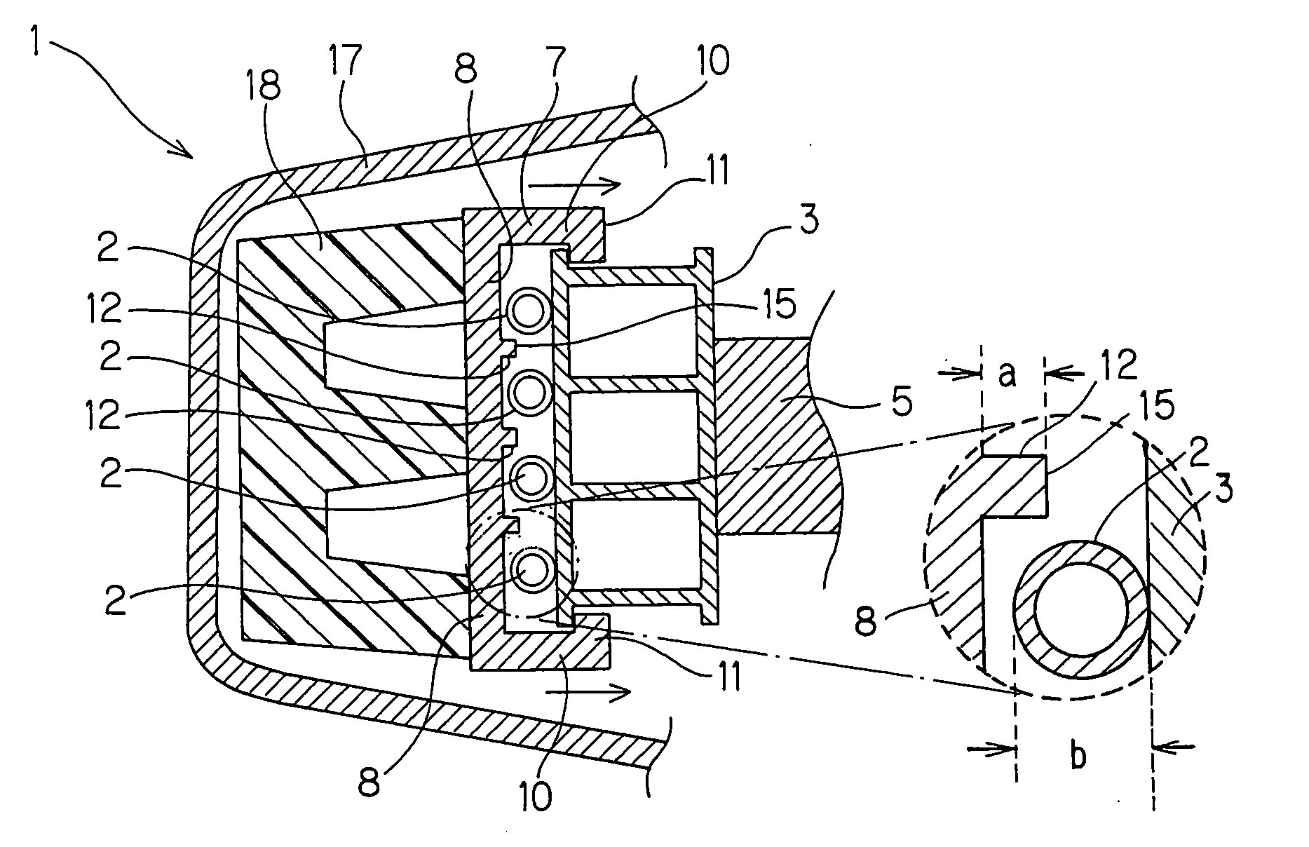
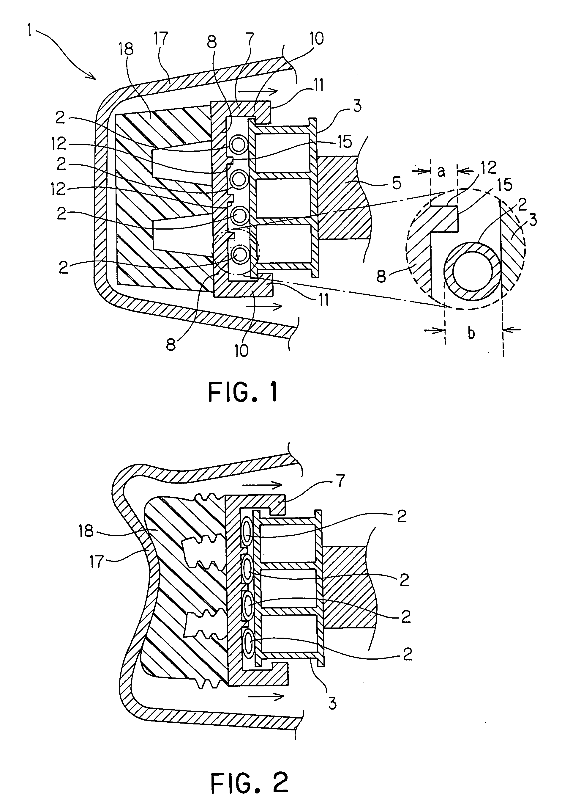
[0041] In a first embodiment of the present embodiment, the load sensing device 1 uses an optical-fiber sensor as the load sensor. FIG. 1 schematically shows a cross sectional view of the load sensing device in this embodiment. FIG. 2 schematically shows a cross sectional view of the load sensing device which is under an application of a forward load.

[0042] In the load sensing device 1 in this embodiment, the optical-fiber sensor 2 serving as load sensor is secured on the front surface of the bumper reinforcement of the vehicle, the bumper reinforcement serving as an inner member 3 or a first member according to the present invention. The optical-fiber sensor 2 is provided to extend in the lateral direction along the inner member 3, that is, the direction extending from side to side of the inner member 3, and turns back at both the left and right ends to be arranged in the up and down direction. The optical-fiber sensor 2 has one end that connects to a not-shown light-emitting mean...

second embodiment

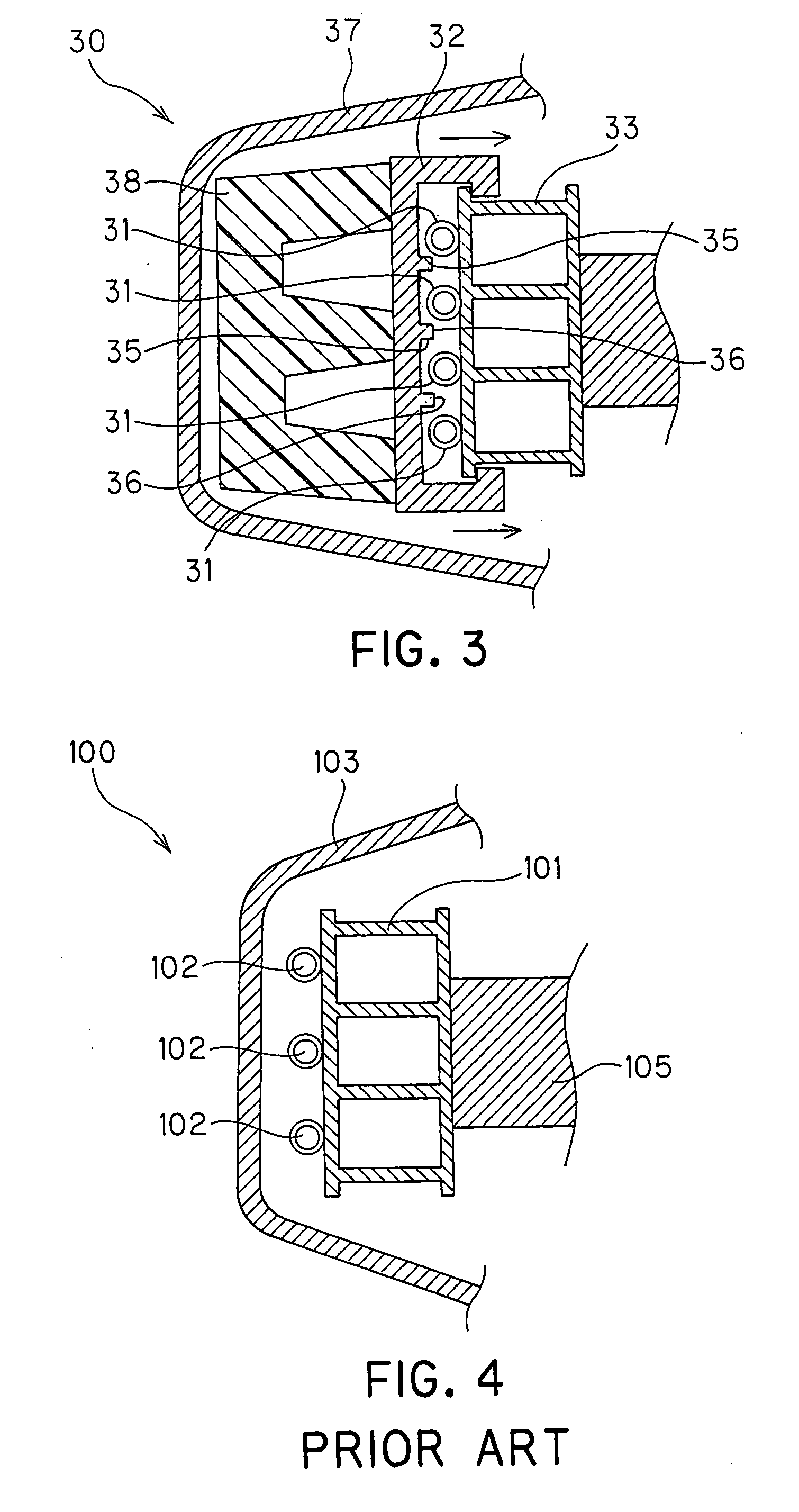
[0050] Referring to FIG. 3, a second embodiment of the present invention will now be described. In the description of the second embodiment, the similar or identical components to those in the first embodiment will be made reference with the same reference numerals as those in the first embodiment.

[0051] A load sensing device 30 according to the second embodiment is the same as the device 1 shown in the first embodiment, except that the load sensor is provided to attach to the load transfer member. FIG. 3 schematically shows a cross sectional view of the load sensing device 30 employed by this embodiment.

[0052] In the load sensing device 30, an optical-fiber sensor 31 serving as the load sensor is secured on the back surface of a load transfer member 32. The optical-fiber sensor 31 is provided extending in the direction from side to side of the load transfer member 32, and turns back at both the left and right ends to be arranged in the up and down direction. The load sensor 31 ha...


PUM

PropertyMeasurementUnit
distanceaaaaaaaaaa
heightaaaaaaaaaa
lengthaaaaaaaaaa

Abstract

A load sensing device comprise an inner member provided at a front part of a vehicle and a load sensor provided at a position before a front of the inner member, in addition to an outer member and a load transfer member. The outer member is provided at the front part of the vehicle so as to be located more frontward than the load sensor so that a space is formed between the outer member and the load sensor. The outer member is in charge of allowing the load sensor to sense, via the outer member, a load applied to a front of the vehicle. The load transfer member, made of a hard material, is disposed adjacently to the load sensor within the space between the outer member and the load sensor. The load sensor is allowed to move along the inner member in the back-and-forth direction of the vehicle.

Description

CROSS REFERENCES TO RELATED APPLICATIONS [0001] The present application relates to and incorporates by reference Japanese Patent application No. 2004-67603 filed on Mar. 10, 2004. BACKGROUND OF THE INVENTION [0002] 1. Field of the Invention [0003] The present invention relates to a load-sensing device which is able to sense a load applied to the front of a vehicle. [0004] 2. Description of the Related Art [0005] In recent years, it has been pointed out that a pedestrian collided with a vehicle may often be damaged by the portion near the vehicle's hood. Development of a vehicle has thus been proposed that has an airbag provided near the vehicle's hood to protect the pedestrian when the pedestrian is collided with the vehicle (for example, refer to Japanese Patent Laid-open Publication No. 2000-264146). [0006] The airbag as described in the publication No. 2000-264146 and the like needs to be provided with a forward-sensing device provided at the front of the vehicle to sense the col...

Claims


Application Information

Patent Timeline
Patent Type & Authority Applications(United States)
IPC IPC(8): G01L5/00B60R19/48B60R21/00B60R21/01B60R21/0136G01L1/24
CPCB60R21/0136G01L5/0052B60R21/34
Inventor SUZUKI, KYOJIRO
Owner TOYOTA JIDOSHA KK
Why Eureka
Try Eureka