
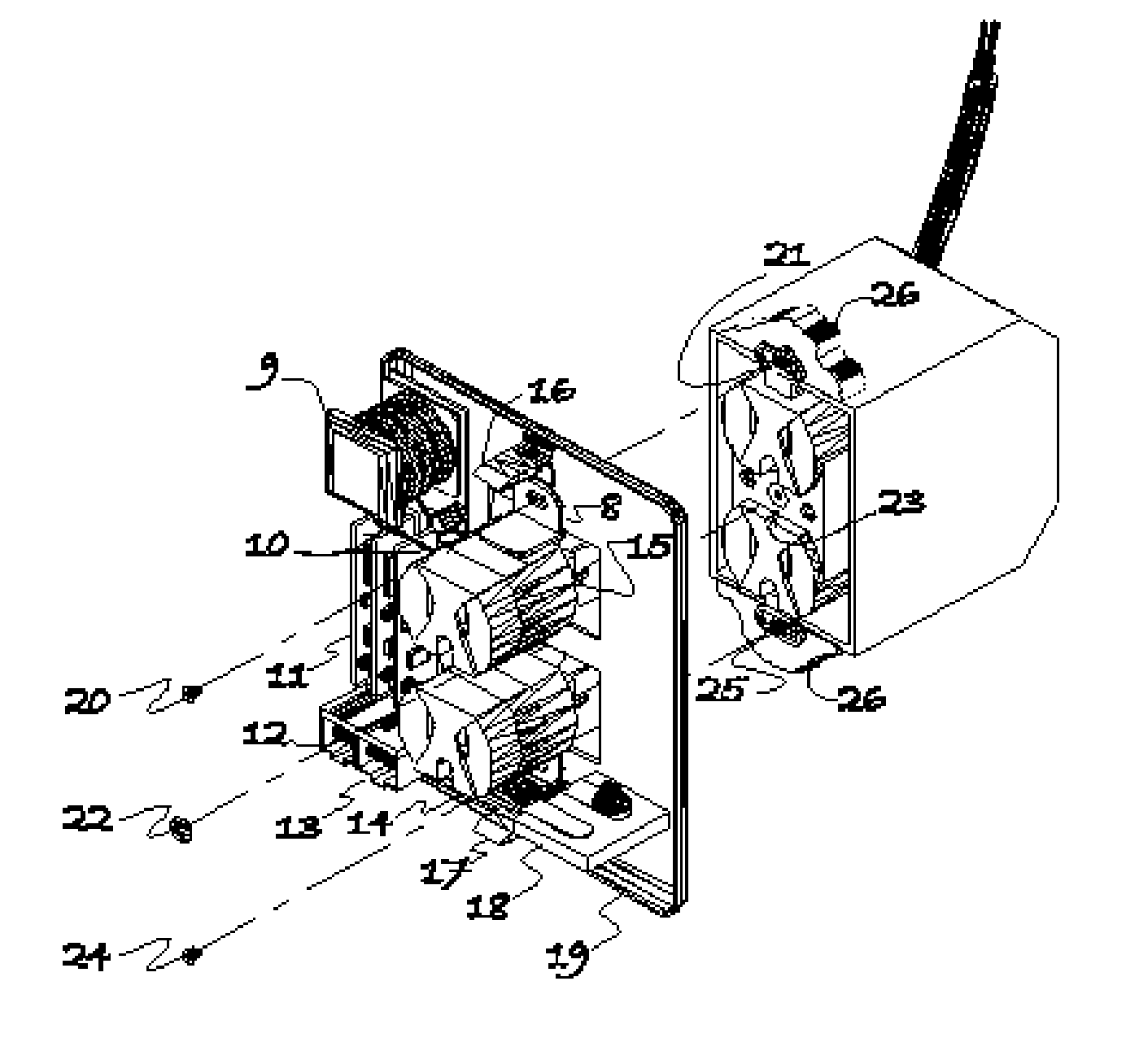
An apparatus that enables low cost installation of a secure and tamper proof assembly that accommodates lifeline support for power line communication devices.

a technology of lifeline support and power line communication, which is applied in the direction of electrical apparatus casings/cabinets/drawers, coupling device connections, casings/cabinets/drawers details, etc., can solve the problems of poor signal coupling, poor connection reliability, and no signal coupling at all, so as to enhance the effect of tampering security

Inactive Publication Date: 2005-09-15
EDGECOM
View PDF21 Cites 17 Cited by
  • Summary
  • Abstract
  • Description
  • Claims
  • Application Information

AI Technical Summary

Benefits of technology

[0009] A novel securely fastened and tamper proof life-line supported indoor power line communication apparatus that overcomes the primary factors that limit adoption of the power line communication and control is disclosed. The power outlet faceplate is removed before the device is directly inserted into the power receptacle either by one or multiple plugs. It is securely fastened to any existing threaded hole or through hole in the power outlet box or power receptacle by using any threaded screws, barbed anchor, plastic anchor, other conventional mounting mechanisms, or any combination thereof. Tamper security is further enhanced by optional mechanisms that require a key to release the faceplate device or by a complete plastic assembly that is securely enclosed by a tamper proof faceplate screw, chemical adhesion, or any other mechanical means including pressure and heat. Life-line support is provided by a rechargeable backup battery or charge cell that is accessible through a lid that is located on the cover of the apparatus.

Problems solved by technology

The technology adaptation cycle of these devices is slow due to stiff opposition from competing wireless technologies and limitations in the physical packaging of power line communication devices.
The former provides a reliable connection at the expense of installation that requires professional assistance for most customers, which is the main limiting factor that inhibits widespread adoption of the technology.
The latter is easy to install, however, this convenience is afforded at the expense of connection reliability.
This drawback causes problems ranging from poor signal coupling to no signal coupling at all; particularly if the unit is accidentally removed from the wall or gradually pulled from the power receptacle because of cable tension.
By contrast, power line communication systems cannot pass signals through uninterruptible power supplies.
Consequently it is expensive to maintain communications during power outages because some alternative form of power, other than low-cost conventional uninterruptible power supplies, must be provided to each unit in the building.

Method used


Image

  • An apparatus that enables low cost installation of a secure and tamper proof assembly that accommodates lifeline support for power line communication devices.
  • An apparatus that enables low cost installation of a secure and tamper proof assembly that accommodates lifeline support for power line communication devices.
  • An apparatus that enables low cost installation of a secure and tamper proof assembly that accommodates lifeline support for power line communication devices.

Examples


Embodiment Construction

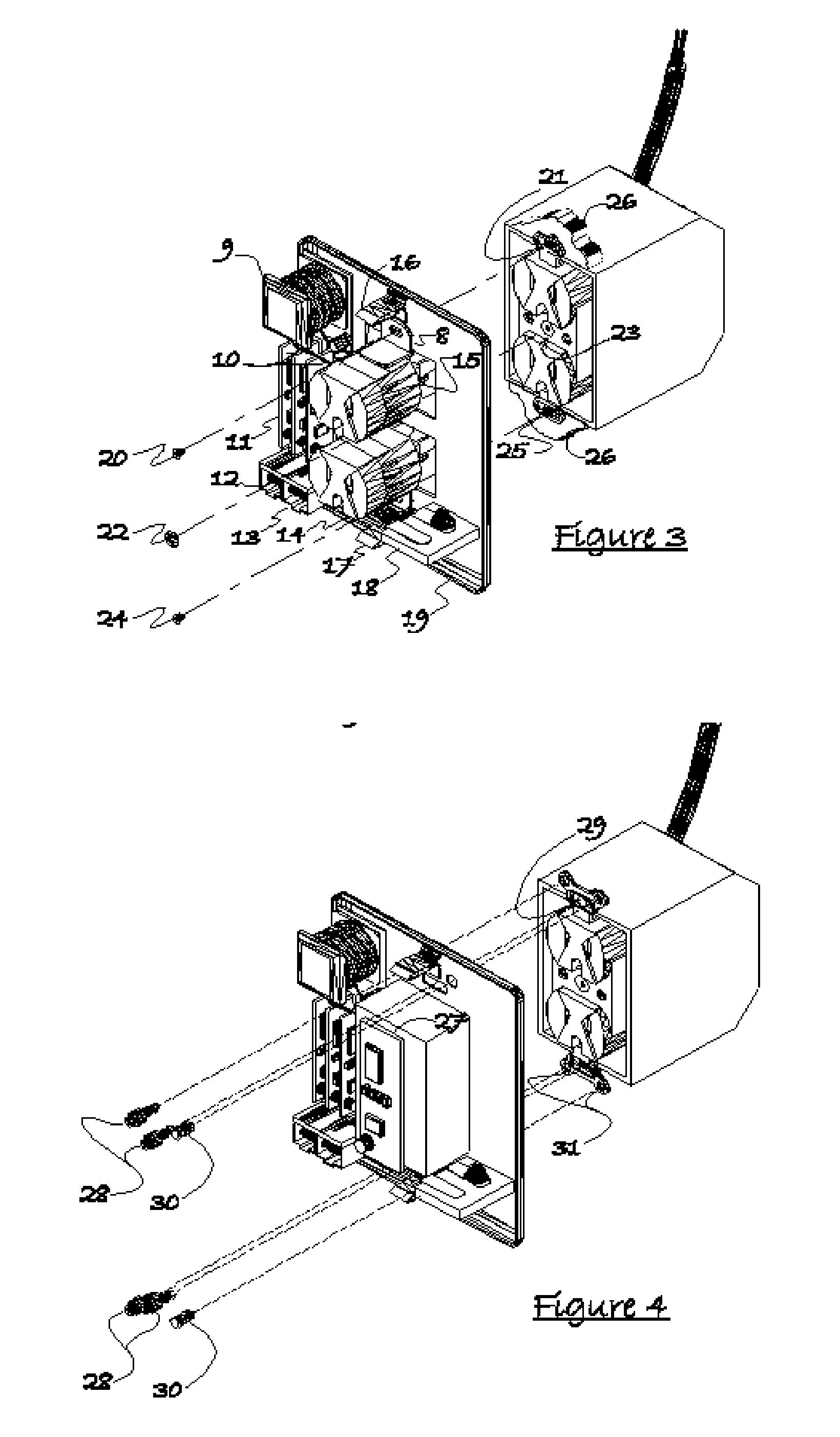
[0022] An expanded illustration of the embodied invention is shown in FIG. 10. This invention discloses the artwork, architecture, mechanical design, housing, ease of installation, and intended use of any assembly or device that plugs into any wall outlet for the purpose of supporting any form of power line control and communication over power lines including any form of data transfer and any form of multi-media such as audio, video, entertainment, telephone, and the like. The device is an enclosed apparatus that contains these components and the primary part that seeks protection in the method that the device installs, which offers considerable savings over any existing artwork or housing.

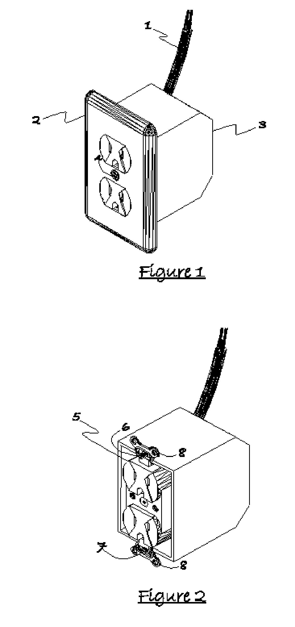
[0023]FIG. 1 shows a standard wall mounted power outlet consisting of the interior building wires that supply the outlet box 1, the power outlet receptacle faceplate 2, the outlet receptacle box 3, and face plate screw 4. The embodied invention is designed in part to replace the outlet receptacle...


PUM


Abstract

A novel apparatus is disclosed that provides a secure, tamperproof, and cordless installation to securely and reliably couple any electronic device directly onto any standard power outlet. The installation is easy, certification free, and does not need to reduce the number of available power outlets. The apparatus also enables reliable and effective signal coupling for power line control and communication devices including X.10, HomePlug, and other proprietary power line based physical layers. For these types of systems the apparatus may provide life line support using a battery or any other form of energy storage. The device is optimally installed directly onto a standard wall outlet by replacing the current face plug with a housing that can be affixed directly onto the duplex outlet with screws that attach to any existing threaded hole used by conventional or other mounting devices within a wall box.

Description

CROSS-REFERENCE TO RELATED APPLICATIONS [0001] Current U.S. Class: 200 / 297, 220 / 3.2, 455 / 402, 455 / 3.01 [0002] Intern'l Class: H01F 027 / 42, H02G 003 / 14 [0003] Field of Search: 174 / 48, 51, 53, 200 / 50.1, 50.14, 51.14, 297, 220 / 3.2, 3.3, 3,7, 307 / 149, 361 / 600, 601, 636, 643, 379 / 142.14, 455 / 3.01, 280, 402 Statement Regarding Federally Sponsored Research or Development [0004] None Reference to Sequence Listing, a Table, or a Computer Program Appendix [0005] None BACKGROUND OF THE INVENTION [0006] Power line based communication and control networks including but not limited to the existing HomePlug, X.10, and broadband access ponits have been entering the main stream market at a relatively slow rate. The technology adaptation cycle of these devices is slow due to stiff opposition from competing wireless technologies and limitations in the physical packaging of power line communication devices. Current indoor power line communication devices include units that require replacement of exis...

Claims


Application Information

Patent Timeline
IPC IPC(8): H01K1/62
CPCH01R2103/00H01R24/76H01K1/62H02G3/14H01R25/006H02G3/12H02G3/18
Inventor THOMPSON, SCOTT RANDALLASKILDSEN, BERNT ASKILD
Owner EDGECOM
Learn More