Multi-platform LED-based aircraft rear position light

a technology of led-based aircraft and rear position lights, which is applied in the direction of landing aids, lighting and heating apparatus, lighting support devices, etc., can solve the problems of reducing the life of incandescent lamps, affecting flight safety, and affecting the safety of passengers

Inactive Publication Date: 2005-09-15
HONEYWELL INT INC
View PDF31 Cites 84 Cited by
  • Summary
  • Abstract
  • Description
  • Claims
  • Application Information

AI Technical Summary

Benefits of technology

[0011] In an exemplary embodiment, the modular components may include an integrated reflector and LED fastener for each side-emitting LED attached to the heat sink. The two integrated reflector and LED fasteners may be fastened together (e.g., in a snap connection) to securely clamp each side-emitting LED in place with respect to the integrated LED and electronic heat sink. In addition, the reflector on each of these fasteners may be configured based on the distribution of the corresponding side-emitting LED to help ensure that the light distribution characteristics of the rear position light device satisfies Federal Aviation Requirements (FARs).

Problems solved by technology

These systems suffer from several disadvantages.
Due to their principles of operation, incandescent lamps have a limited life compared to other light sources (e.g., fluorescent, solid-state, and high intensity discharge lights).
The harsh environment under which an aircraft operates can further reduce the life of incandescent lamps.
Since aviation safety regulations require that the aircraft's position lights be functioning when the aircraft is operating at night, the frequent failures of incandescent positioning lights may result in delayed flight departures as well as high maintenance costs due to replacement.
However, such systems are not suitable as a direct replacement (either in form or fit) for existing incandescent lights.
In addition, known LED-based position lights have been designed as point solutions—not as a common solution suitable for various platforms.
Another problem associated with known LED-based position lights is the variations in photometric distributions associated with LEDs.

Method used


Image

  • Multi-platform LED-based aircraft rear position light
  • Multi-platform LED-based aircraft rear position light
  • Multi-platform LED-based aircraft rear position light

Examples


Embodiment Construction

[0020] Exemplary embodiments of the present invention are disclosed in the following description.

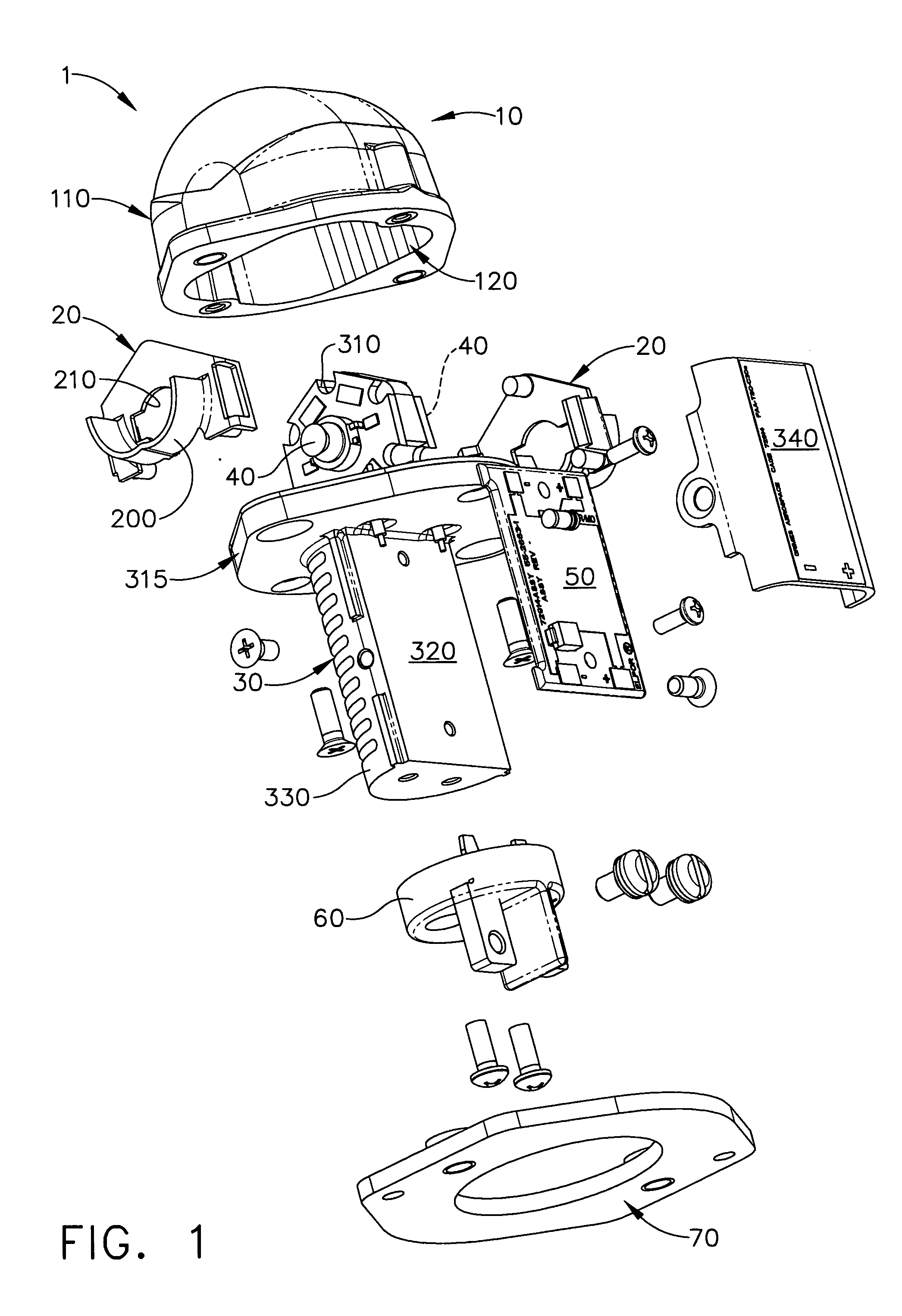
[0021] The present invention is directed to a rear position light device to be mounted on an aircraft (particularly, at the aft of the aircraft) to provide information regarding the aircraft's relative position to other aircraft operating in the same general airspace. According to exemplary embodiments, the rear position light device utilizes solid state light sources, which have a longer operational life and generate less heat than the incandescent light sources used in conventional forward position lighting systems. In addition, this position light device may be portable and capable of being mounted on different types of platforms, in accordance with exemplary embodiments.

Federal Aviation Regulations (FARs)

[0022] At this point it may be beneficial to describe some of the requirements imposed on aft position lights by the Federal Aviation Regulations (FARs). It should be noted that ...


PUM


Abstract

An aircraft rear position light device (1) has a modular configuration. The device utilizes solid-state light sources. In an exemplary embodiment, the light sources are side-emitting light-emitting diodes (LEDs) (40), which are attached to a heat sink (30). A reflector (200) is positioned next to each of the LEDs. The device further includes an outer lens (10) with an integrated cut-off shield (110) and optical treatments (120). The configuration of LEDs and reflectors, in conjunction with the cut-off shield and optical treatments, allows the emitted light to satisfy predetermined minimum and maximum angular intensity requirements. An electronics module (50) is also attached to the heat sink to connect the LEDs to a power source in the aircraft. Electronic updates may be made by replacing the electronics module.

Description

RELATED APPLICATION [0001] This application claims priority under 35 U.S.C. § 119(e) of U.S. Provisional Application No. 60 / 552,209 filed on Mar. 12, 2004, the entire contents of which are herein incorporated by reference.FIELD OF THE INVENTION [0002] The present invention is directed to position lighting systems on aircraft, and more particularly to rear position lights utilizing solid-state light sources. BACKGROUND OF THE INVENTION [0003] In order to prevent collisions with other aircraft, a variety of lights are mounted on the exterior of an aircraft in order to indicate its relative position to the other aircraft in the same general airspace. Such lighting systems include a rear (or aft) position lighting system, which typically comprises a white light installed on the aft of an aircraft. The aircraft's lighting systems also include forward position lights, comprising a red light on the port wing and a green light on the starboard wing. Other aircraft operating in the vicinity ...

Claims


Application Information

Patent Timeline
Patent Type & Authority Applications(United States)
IPC IPC(8): B64D47/02B64D47/06
CPCB64C2027/8236B64D47/06F21V5/04F21V5/046B64D2203/00F21V29/004F21Y2101/02F21W2101/06F21V7/0091F21V29/70F21Y2115/10F21W2107/30
Inventor MACHI, NICOLO F.SINGER, JEFFREY M.MCKENZIE, MARK A.
Owner HONEYWELL INT INC
Why Eureka
Try Eureka