Use of variable ratio couplers for network protection and recovery

a technology of network protection and recovery, applied in the direction of multiplex communication, transmission monitoring, instruments, etc., can solve the problems of system significant link insertion loss, system restoration difficulty, and inability to includ

Active Publication Date: 2005-09-15
GOOGLE TECH HLDG LLC
View PDF5 Cites 29 Cited by
  • Summary
  • Abstract
  • Description
  • Claims
  • Application Information

AI Technical Summary

Problems solved by technology

However, the optical switch does not include any arrangement for switching back from the secondary path to the primary path after the primary path has been restored.
Restoration in this manner can be difficult because the head end and the optical node may be located 50 to 100 kilometers apart.
However, by employing two switches and four tap couplers, the system incurs significant link insertion losses (e.g., up to about 6 dB).

Method used


Image

  • Use of variable ratio couplers for network protection and recovery
  • Use of variable ratio couplers for network protection and recovery
  • Use of variable ratio couplers for network protection and recovery

Examples


Embodiment Construction

[0021] Persons of ordinary skill in the art will realize that the following description of the present disclosure is illustrative only and not in any way limiting. Other embodiments of the invention will readily suggest themselves to such skilled persons having the benefit of this disclosure.

[0022] An exemplary optical transmission system having variable ratio couplers for point-to-point unidirectional and bi-directional fiber optic transmission is disclosed. The optical transmission system replaces commonly used 1×2 optical switches with variable ratio couplers.

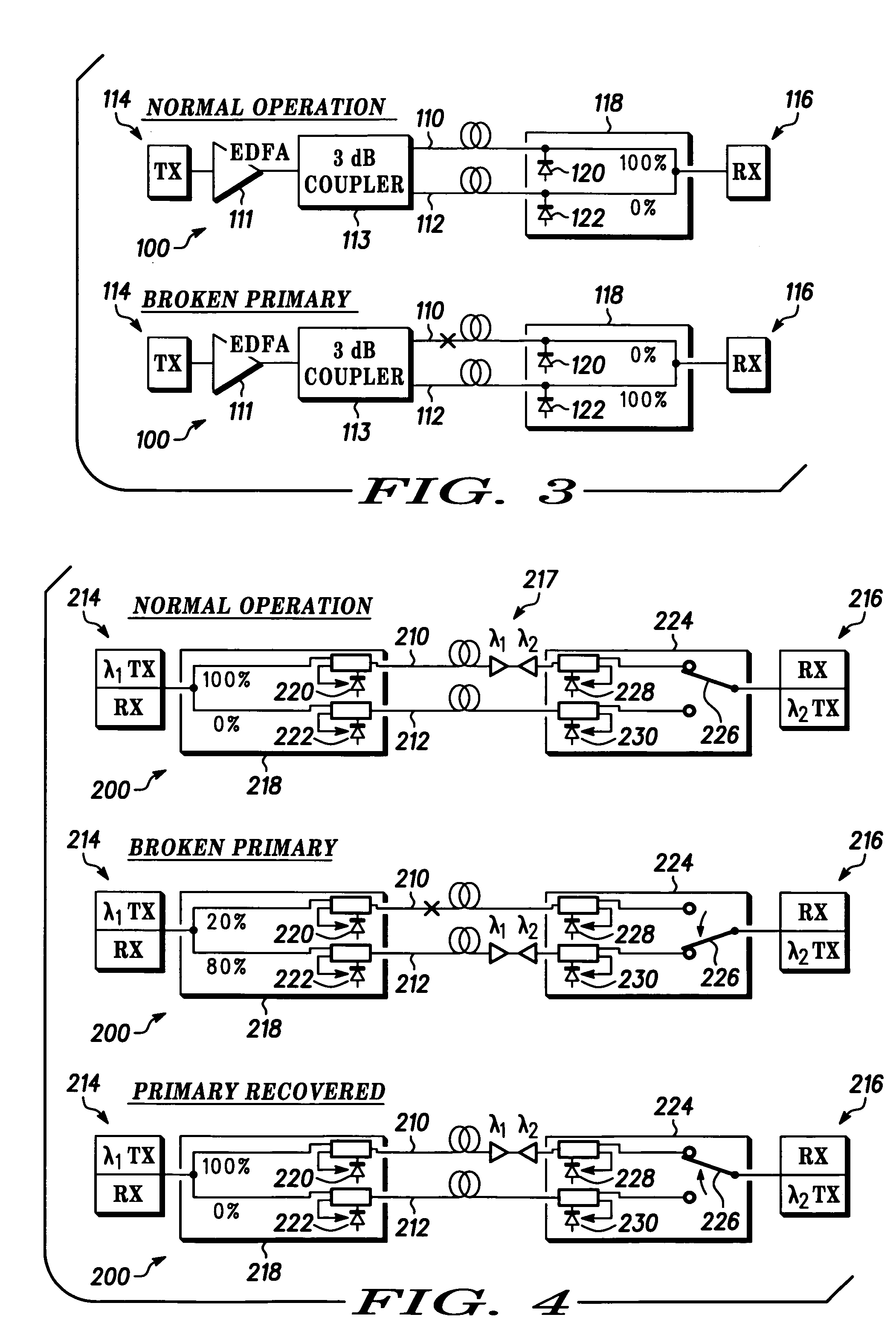
[0023]FIG. 3 illustrates an exemplary embodiment of an optical transmission system 100. The optical transmission system 100 includes a primary path 110 and a secondary path 112 disposed between a head end transmitter 114 and an optical node end 116. One or more optical amplifiers, such as an Erbium doped fiber amplifier (EDFA) 111 can be provided in the optical transmission system. A coupler, such as 3 dB coupler 113, is p...


PUM


Abstract

The disclosure is directed toward an optical transmission system comprising a primary path disposed between a first end and a second end. The primary path is configured to transmit optical signals between the first end and the second end. A secondary path is disposed between the first end and the second end. The secondary path is configured to transmit optical signals between the first end and the second end, e.g., in the event of a break in the primary path. A first variable ratio coupler is coupled to the primary path and the secondary path between the first end and the second end. The first variable ratio coupler is configured to adjust a coupling ratio between the primary path and the secondary path.

Description

BACKGROUND OF THE INVENTION [0001] The present invention relates to protection of point-to-point unidirectional and bi-directional fiber-optic transmission lines, and particularly to replacement of commonly used optical switches with variable ratio couplers for the protection of the fiber-optic transmission lines and up to about 3 dB insertion loss improvements. [0002] Currently, transmission systems employed in the cable television (CATV) industry provide two-way transmission of information (e.g., video, audio, multimedia and / or data) between a head end and a plurality of subscribers. The head end transmits the information destined for individual subscribers in optical format (i.e., downstream information) through one or more fiber optic links to one or more optical nodes. Each node converts the optically-formatted downstream information into electrical signals for distribution, typically via a coaxial cable plant having a tree and branch architecture, to individual subscribers. In...

Claims


Application Information

Patent Timeline
Patent Type & Authority Applications(United States)
IPC IPC(8): H04B10/08
CPCH04B10/032
Inventor WANG, SHAMINO Y.JASTI, CHANDRA S.
Owner GOOGLE TECH HLDG LLC
Why Eureka
Try Eureka