
Adaptive security and protective barriers and traffic control speed bumps

a technology of security protection and speed bumps, applied in roadway safety arrangements, roadways, construction, etc., can solve the problems of higher initial cost of installation of barriers disclosed herein, and achieve the effects of fewer personnel, increased initial cost of installation, and safe operation

Inactive Publication Date: 2005-09-15
OMNITEK PARTNERS LLC
View PDF19 Cites 34 Cited by
  • Summary
  • Abstract
  • Description
  • Claims
  • Application Information

AI Technical Summary

Benefits of technology

[0010] A need therefore exists for novel security and protective barrier technologies that address the aforementioned shortcomings of the currently available roadway barriers, such as those barriers employing a concrete block design. The barriers disclosed herein have many applications, such as highly effective security barriers for checkpoints that could be operated safely by significantly fewer personnel and that could also be used as barriers for barricading buildings and other sensitive areas. The barriers disclosed herein also utilize existing and mass-produced off-the shelf components. They can be constructed as passive barriers or readily be equipped with simple and readily available sensory inputs to convert them to sophisticated security and protective barriers. The barriers disclosed herein may also be retracted to be hidden from sight in a fraction of a second and may also be deployed in a fraction of a second from a remote location. The barriers disclosed herein can have a higher initial cost to install. However, the reduction in the cost of operating security checkpoints and barricades in terms of the significant reduction in the number of security personnel and the cost of transporting the barriers back and forth to the storage can quickly recover the extra cost as compared to barriers of the prior art, such as concrete barriers. In addition, the barriers disclosed herein have a significant commercial market not only in the areas of security and protective barriers, but also in the area of speed control, such as for “smart speed bumps” that allow a smooth drive for vehicles that are driving at speeds below the area limits and can deploy to regulate the speed of vehicles traveling above the area limits.

Problems solved by technology

The barriers disclosed herein can have a higher initial cost to install.

Method used


Image

  • Adaptive security and protective barriers and traffic control speed bumps
  • Adaptive security and protective barriers and traffic control speed bumps
  • Adaptive security and protective barriers and traffic control speed bumps

Examples


Embodiment Construction

[0043] Although this invention is applicable to numerous and various types of surfaces, it has been found particularly useful in the environment of roadways. Therefore, without limiting the applicability of the invention to use on roadways, the invention will be described in such environment. However, those skilled in the art will appreciate that the speedbumps and barriers of the present invention also have utility for use on other surfaces, including natural surfaces, such as grass and dirt.

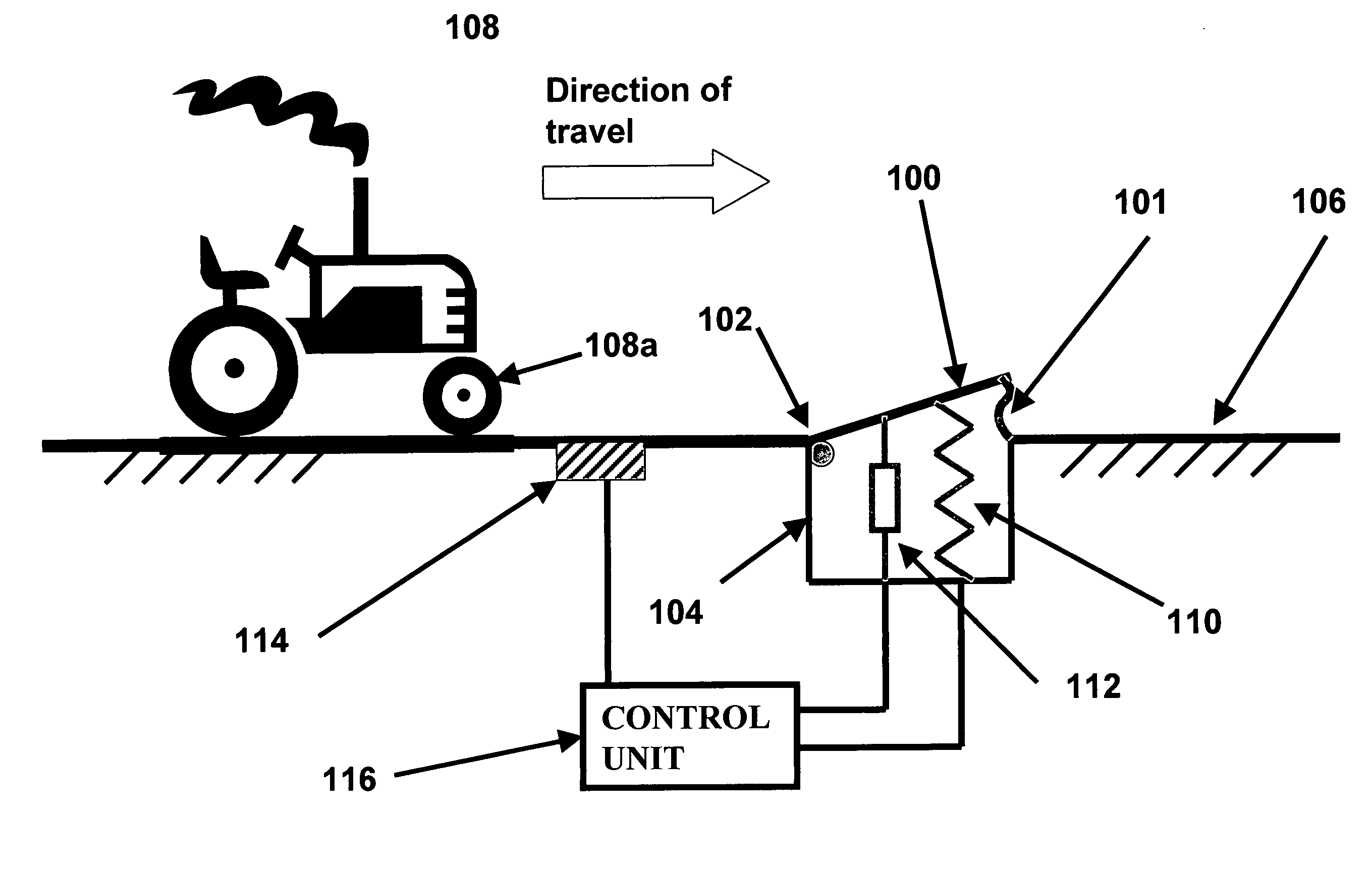
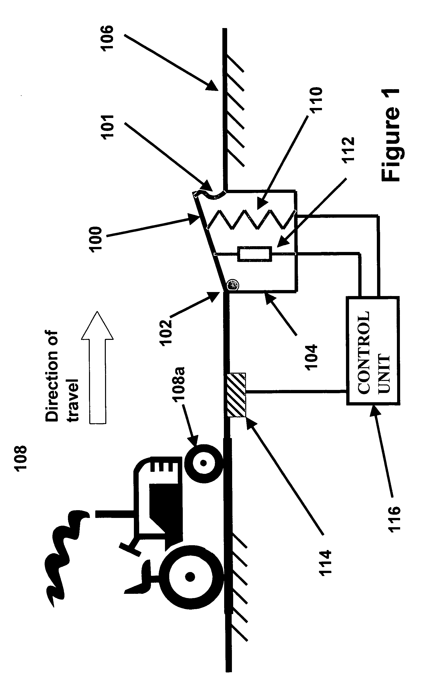
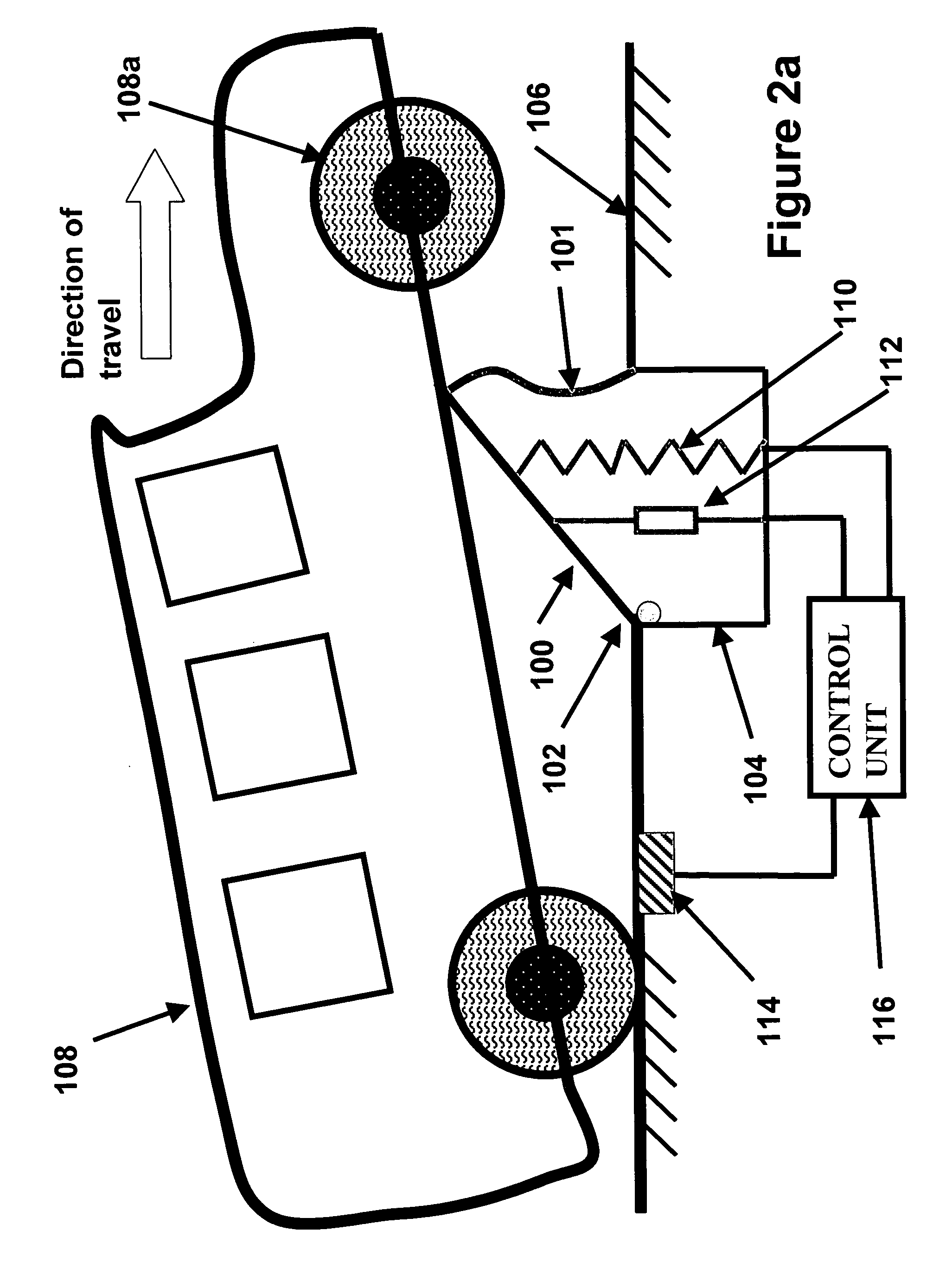
[0044] A basic operation of an embodiment of a barrier of the present invention is shown in the schematic of FIG. 1. In FIG. 1, the operation of the security barrier acting as a traffic speed control device (alternatively referred to herein as a “speedbump”) is shown. Two of the major variations to this device for providing “deployable vehicular security barriers” and “deployable high-speed car (truck) bomb stopping barriers” are described below.

[0045] The speedbump includes at least one pane...


PUM


Abstract

A method for at least slowing a vehicle moving along a surface is provided. The method including; providing one or more panels capable of extending above the surface; and deploying the one or more panels from the surface into a position extended from the surface.

Description

CROSS-REFERENCE TO RELATED APPLICATIONS [0001] This application is related to co-pending U.S. patent application Ser. No. 10 / 372,496 entitled “Roadway For Decelerating and Accelerating a Vehicle Including an Aircraft,” filed on Feb. 24, 2003, the contents of which are incorporated herein in its entirety by this reference.BACKGROUND OF THE INVENTION [0002] 1. Field of the Invention [0003] The present invention relates generally to vehicle barriers and speed bumps, and more particularly, to an adaptive security and protective barrier and traffic control speed bumps. [0004] 2. Prior Art [0005] Concrete blocks of various designs have long been used as security barriers to barricade sensitive areas and buildings or to provide the means to slow down and control traffic for inspection and / or identification checking or other similar security reasons. Such barriers are also used on a segment of a road to form a maze to force vehicles to slow down; to provide the means to prevent vehicles fro...

Claims


Application Information

Patent Timeline
IPC IPC(8): E01F15/00E01F9/529G08G
CPCE01F13/123E01F9/047E01F9/529
Inventor RASTEGAR, JAHANGIR S.SPINELLI, THOMAS
Owner OMNITEK PARTNERS LLC
Learn More