Deep refuse container

a deep, refuse technology, applied in the field of refuse containers, can solve the problems of time-consuming and thus expensive process of refuse collection, frequent emptying cycles, etc., and achieve the effects of reducing the required emptying frequency of refuse containers, saving time and space, and increasing volum

Inactive Publication Date: 2014-03-18
KANERVO JANNE
View PDF9 Cites 0 Cited by
  • Summary
  • Abstract
  • Description
  • Claims
  • Application Information

AI Technical Summary

Benefits of technology

[0016]Significant advantages can be achieved with the present invention when compared to the prior art solutions. The deep refuse container according to the present invention may comprise larger volume for garbage, which, in turn, may decrease the required emptying frequency of the refuse containers. One deep refuse container according to the present invention may also comprise more than one inner space for garbage, which may enable several waste types to be collected in the same container. Naturally, this feature may save time and space, if one large container could be used for various waste types.
[0017]In addition, the deep refuse container according to the present invention may be emptied by using an automated emptying means, such as garbage collecting vehicle with automated sidearm. This may enable the present invention to be utilized in areas, where a curbside collection system is used. Naturally, these advantages of the present invention may bring savings in time, material and space, when less refuse containers, garbage collecting vehicles and, therefore, fewer personnel may be needed.
[0018]Finally, the cone-shaped form of the present invention may facilitate stacking and transporting of the frame part and / or body part, which may save space when storing and transporting body parts and / or frame parts.

Problems solved by technology

Nevertheless, because of the required emptying frequency and the number of the refuse containers to be emptied, refuse collecting is time-consuming and thus expensive process.
Even though the process is lighter than the former way, frequent emptying cycles are still required, which, in turn, requires great number of garbage collecting vehicles and, thus personnel to handling the process.

Method used


Image

  • Deep refuse container
  • Deep refuse container

Examples


Embodiment Construction

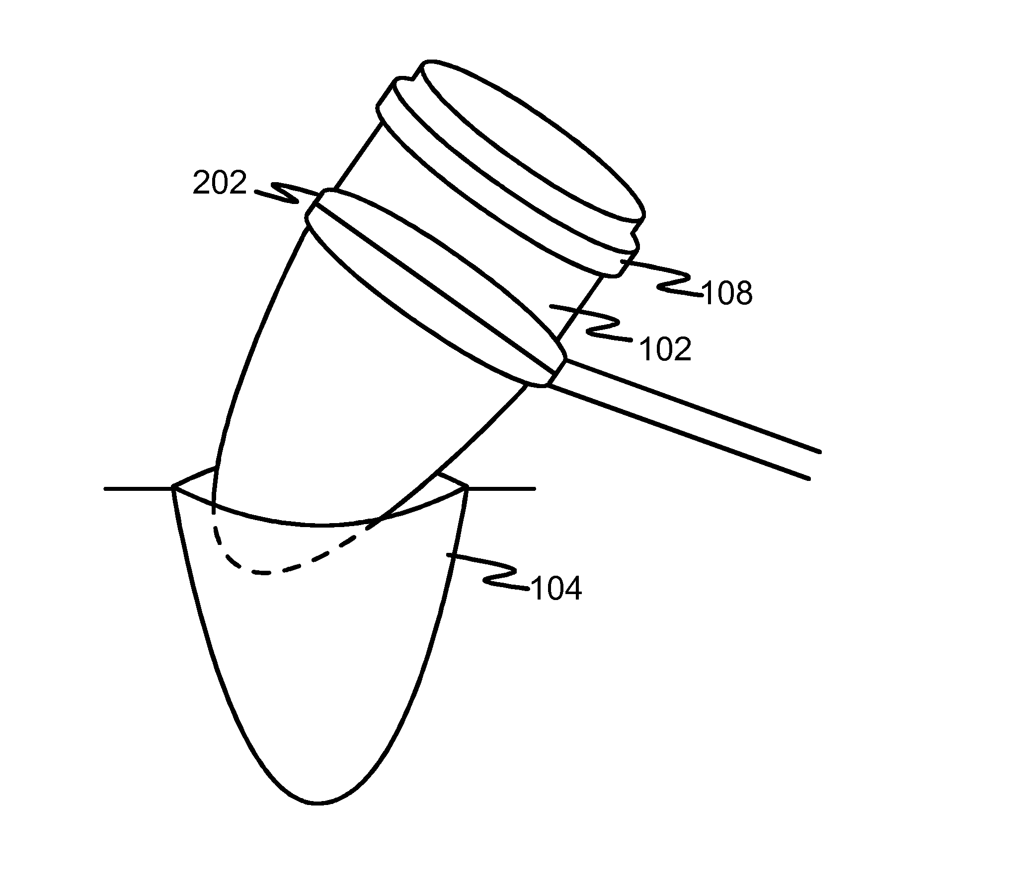
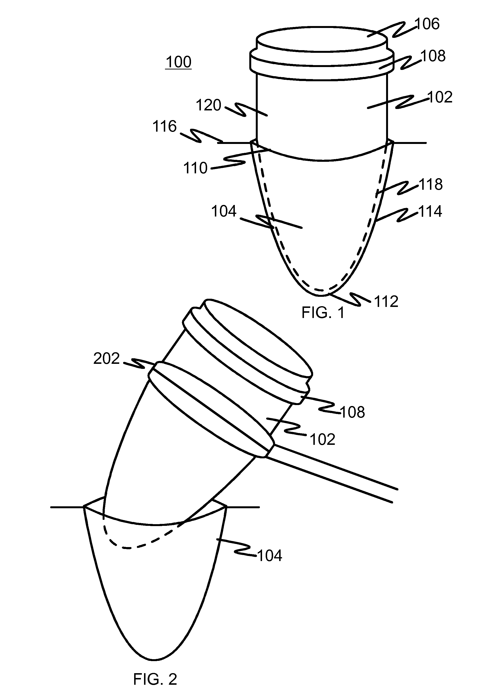
[0022]FIG. 1 illustrates a side view of a deep refuse container in use according to an embodiment of the present invention. The deep refuse container 100 of the present invention comprises a body part 102 and a frame part 104. The body part 102 comprises at least one inner space 106 for garbage and at least one contact part 108 for automated emptying means. The frame part 104 comprises an open upper end 110, a lower end 112 and at least one side 114 for supporting the body part 102.

[0023]When in use, the frame part 104 is disposed below the ground level 116 so that the upper end 110 of the frame part 104 is substantially at the same level with the ground level 116 or above the ground level 116. The body part 102 is disposed into the frame part 104 so that a lower portion 118 of the body part 102 locates inside the frame part 104 and an upper portion 120 of the body part 102 locates above the frame part 104.

[0024]The frame part 104 of the present invention can be made of any suitable...


PUM


Abstract

A deep refuse container with a greater volume for garbage, container can be emptied by using automated elements. The deep refuse container includes a body part having at least one inner space for garbage, and a frame part including an open upper end, a lower end and at least one side for supporting the body part. The frame part of the deep refuse container of is disposed below the ground level so that the upper end of the frame part is substantially at the same level with the ground level or above the ground level. The body part of the deep refuse container is disposed into the frame part so that a lower portion of the body part locates inside the frame part and upper portion of the body part locates above the frame part. The body part is further provided with one or more contact parts for automated emptying elements.

Description

TECHNICAL FIELD[0001]Generally, the invention relates to a refuse container. More specifically, the invention relates to a deep refuse container.BACKGROUND TECHNOLOGY[0002]Waste management, such as collecting, transporting, processing and recycling, is one of the basic requirements in today's society. In addition, domestic households have been taught to sort their garbage e.g. organic, paper, metal and glass waste from the other waste, which has increased the number of refuse containers per domestic household or collecting unit.[0003]In US, Australia and Canada, for example, a curbside collection (or kerbside collection) is a system typically used in urban and suburban areas for waste collection from domestic households. Waste materials are usually collected in large bins, which are disposed in a curbside nearby a house or collecting unit they are related to. Generally, differently colored refuse containers are assigned to different type of waste.[0004]Emptying of refuse containers ...

Claims


Application Information

Patent Timeline
Patent Type & Authority Patents(United States)
IPC IPC(8): B65D88/76
CPCB65F1/1447B65F2230/00B65F1/122
Inventor KANERVO, JANNE
Owner KANERVO JANNE
Why Eureka
Try Eureka