
Blind rivet nut

a technology of blind rivets and nuts, which is applied in the direction of screws, pins, fastening means, etc., can solve the problems of increased manufacturing costs, increased manufacturing costs, and increased manufacturing costs of tooling for a larger number of people, so as to prevent or reduce the rotation of blind rivets, enhance the grip capability of blind rivets, and deforms more readily

Inactive Publication Date: 2005-09-15
NEWFREY
View PDF10 Cites 30 Cited by
  • Summary
  • Abstract
  • Description
  • Claims
  • Application Information

AI Technical Summary

Benefits of technology

[0013] An advantage of the invention is that it permits blind rivet nuts to be used in situations where the thickness of the material, through which the blind rivet nut passes, varies, thus overcoming the need for a great variety of lengths of blind rivet nut.
[0014] Preferably the or each line of weakness is a groove formed in a portion of the hexagon body and is dimensioned and arranged so that material deforms more readily so as to enhance the grip capability of the blind rivet nut.
[0015] Ideally the blind rivet is a closed end blind rivet nut and the or each groove is / are machined or formed, e.g., by rolling in an outer surface of its collapsible portion.
[0016] In the case of a blind rivet nut with a cylindrical body the depth of the groove is typically between 0.1 and 0.3 mm. In the case of a hexagon shape the depth of the groove of between 0.1 mm and 0.05 mm typically is where the wall thickness of the body is at a minimum at the across flats dimension and accordingly is deeper across the corners.
[0017] Advantageously the grooves are annular recesses formed in a plane parallel with the flange. More than one groove may be provided, in which instance, upon deformation of the body of the blind rivet nut that occurs on setting, radial expansion is exaggerated at a plurality of locations. This results in another advantage of the invention, attributable to the fact that additional lateral grip is provided by the portion(s) of the rivet nut that deform(s) when the, or each, line of weakness is defined in the portion of the rivet nut that sits within the aperture. Where there is slight play between the blind rivet nut and internal sides of the aperture, radial expansion of material forming the body of the blind rivet nut will tend to reduce this play, thereby not only gripping materials axially in a direction parallel to the axis of the blind rivet but also laterally, so as to prevent or reduce rotation of the blind rivet in the aperture. This particular feature is considered to be a benefit when using the blind rivet nut in a plurality of layers of material.
[0018] It can be envisaged that where the blind rivet nut is employed in several layers of material, relative centres of one hole to another, can vary. In order to accommodate these differences in hole centre location, so as to ensure registration of the holes or apertures, it is common practise to increase hole or aperture sizes in the sheet metals pressings. These holes are sometimes referred to as being oversize.

Problems solved by technology

This requirement for several different lengths of blind rivet nut carries with it the attendant risk that an unsuitable blind rivet nut could be used in a particular thickness of panels with the resultant risk of improper insertion or even failure.
Moreover there is associated with a wide selection of blind rivet nuts, the additional cost of manufacturing, the additional cost of manufacturing tooling for a larger number of blind rivet nut lengths and the associated costs of storage, labeling and distribution.

Method used


Image

  • Blind rivet nut
  • Blind rivet nut
  • Blind rivet nut

Examples


Embodiment Construction

[0036] The following description of the is merely exemplary in nature and is in no way intended to limit the invention, its application, or uses.

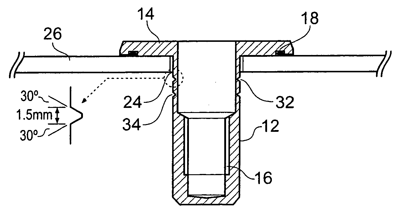
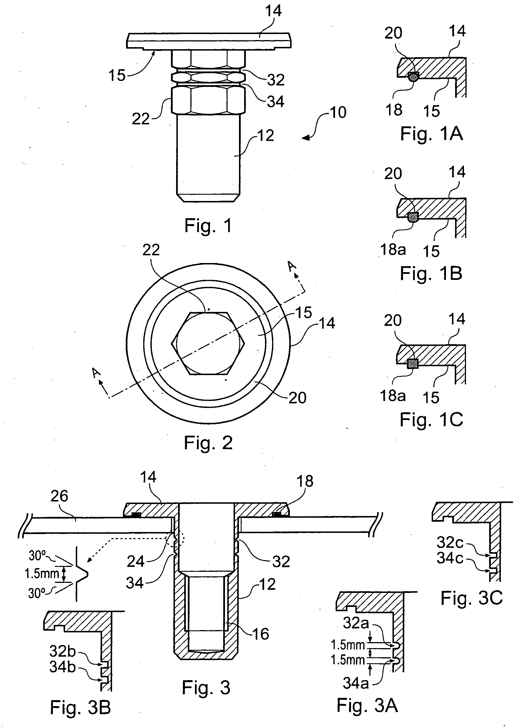
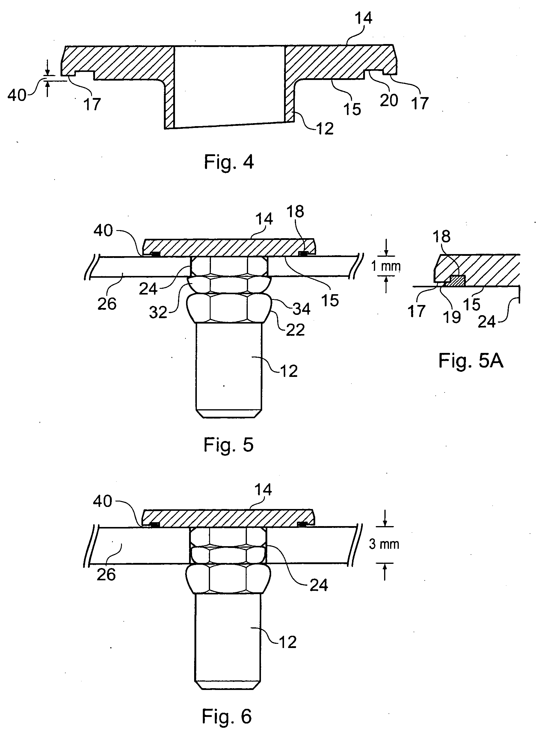
[0037] Referring to the Figures there is shown a blind rivet nut 10 having a body 12 and a flange 14. Blind rivet nut 10 has an internally threaded portion 16 and is in the form of a fully machined, standard closed end blind rivet nut with a hexagon form 22 along the portion of the shank of the blind rivet nut which abuts the underside face 15 of flange 14. Formed or machined in face 15 is an annular recess 20 which forms a location for the seal 18 as shown in FIG. 1A. Alternative forms of seal are in FIGS. 1B showing hemispherical shape 18a and 1C showing a square seal 18b.

seal are in FIGS. 1B showing hemispherical shape 18a and 1C showing a square seal 18b.

[0038] The hexagon form 22 of the blind rivet nut 10 is shaped so as to enter corresponding hexagon shaped holes or apertures 24 in work-piece panel 26 and on setting, provides resi...


PUM


Abstract

The present invention relates to a blind rivet nut. Blind rivet nuts are used to connect items to surfaces of materials, such as roof racks to automobiles, and have proven to be extremely reliable. However, difficulties occur when attempting to connect to several layers of materials or when material thickness increase, as it has been necessary to increase hole size in order to ensure hole registration and this can cause sealing problems. The invention provides a blind rivet nut capable of being used through one or several layers with improved grip capability and improved sealing ability preventing ingress of moisture. Lines of weakness in the form of grooves are formed in a portion of the body of the blind rivet nut so that material deforms selectively thereby improving the grip of the blind rivet nut. A flange has an annular recess that enables an O-ring seal to deform more efficiently, giving a larger ‘footprint’ than was previously possible thereby enhancing sealing.

Description

CROSS-REFERENCE TO RELATED APPLICATIONS [0001] This application claims the benefit of British Patent Application No. GB 0401206.8 filed Jan. 21, 2004. The disclosure of the above application is incorporated herein by reference. BACKGROUND OF THE INVENTION [0002] The present invention relates to a blind rivet nut. More particularly, the present invention relates to a blind rivet nut that has improved grip capability and an improved seal. [0003] Blind rivet nuts are used in thin sheet applications as a means of thread reinforcement and in applications to which a secondary rivet part (bolt) is secured. In some instances these blind rivet nuts are used, for example, to connect an attachment for a rack to the roof of an automobile, where the blind rivet nut is of the so-called closed end variety. [0004] A blind rivet nut typically has an elongate body, that is generally cylindrical or hexagonal in cross section, and hollow for the major part of its length, with one end being either close...

Claims


Application Information

Patent Timeline
IPC IPC(8): F16B19/00F16B37/04F16B33/00F16B37/06
CPCF16B33/004F16B19/008
Inventor DAVIES, JOHN DAVIDJONES, STEVEN VICTORWEEKS, GEOFFREY
Owner NEWFREY
Features
  • Generate Ideas
  • Intellectual Property
  • Life Sciences
  • Materials
  • Tech Scout
  • Unparalleled Data Quality
  • Higher Quality Content
  • 60% Fewer Hallucinations
Learn More