
Tricep and bicep exercise bar

a technology for exercising bars and triceps, applied in the field of exercise equipment, can solve the problems of wrist rotation of prior art units while raising and lowering the exercise bar, and achieve the effect of improving the stability of the exercise bar

Inactive Publication Date: 2005-09-15
DE LANO MICHAEL MARTIN
View PDF7 Cites 42 Cited by
  • Summary
  • Abstract
  • Description
  • Claims
  • Application Information

AI Technical Summary

Benefits of technology

[0014] B.) To provide a smooth rotation, clockwise and counterclockwise, of each handlegrip individually, while raising and lowering the exercise bar during the course of it's intended use.
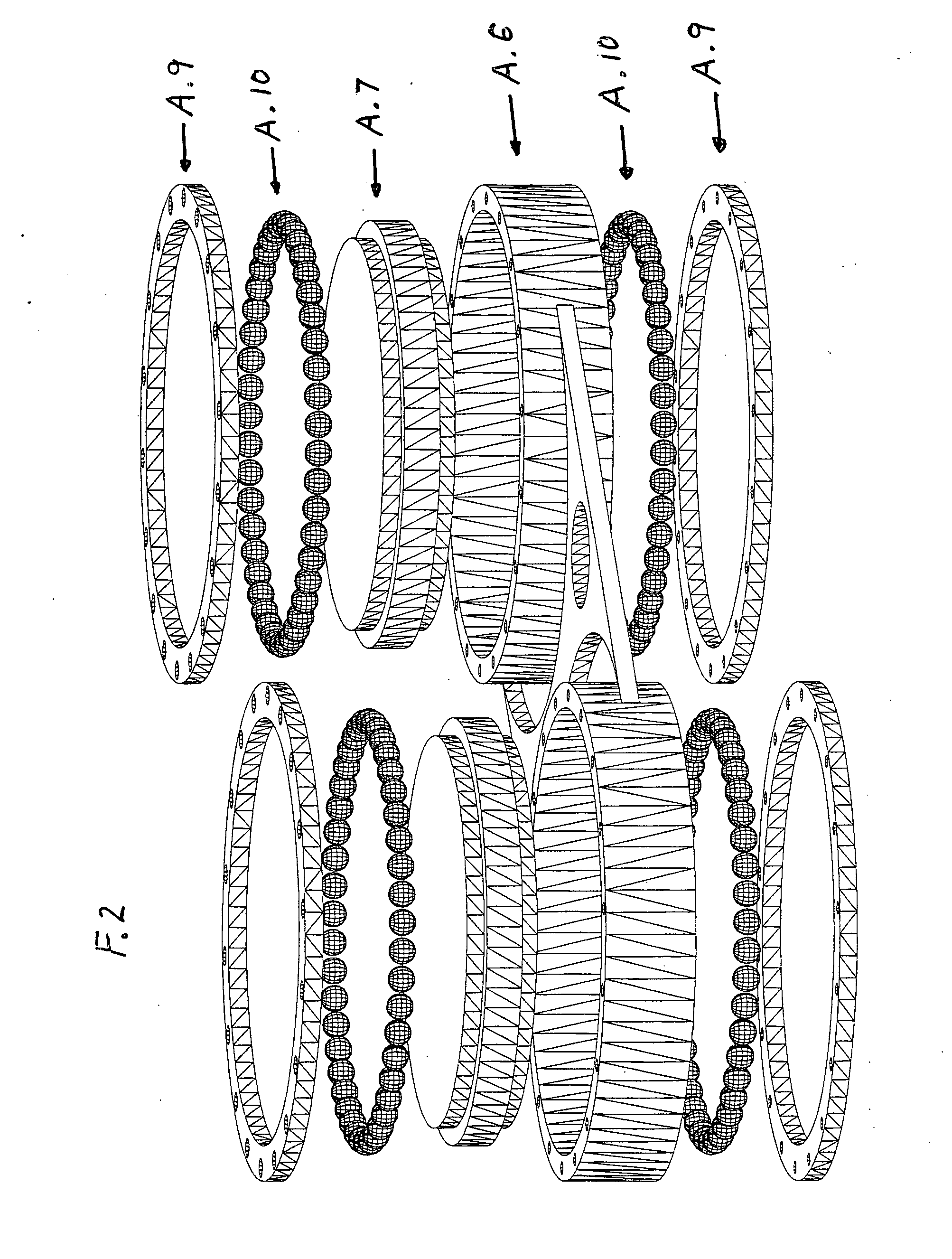
[0018] The unique feature of my invention allows for the necessary, inward and outward, rotation of the wrists of each hand by the use of handle grips secured inside a set of rings that sandwitch a full set of ball bearings that provide a smooth rotation of the wrists while raising and lowering the exercise bar during it's intended use.

Problems solved by technology

These prior art units, however, are not capable of rotation of the wrists while raising and lowering the exercise bar.

Method used


Image

  • Tricep and bicep exercise bar
  • Tricep and bicep exercise bar
  • Tricep and bicep exercise bar

Examples


Embodiment Construction

FIG. 1—Preferred Embodiment

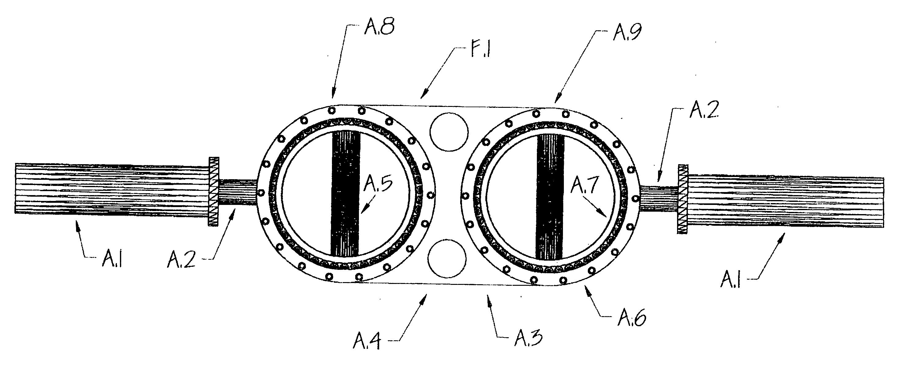
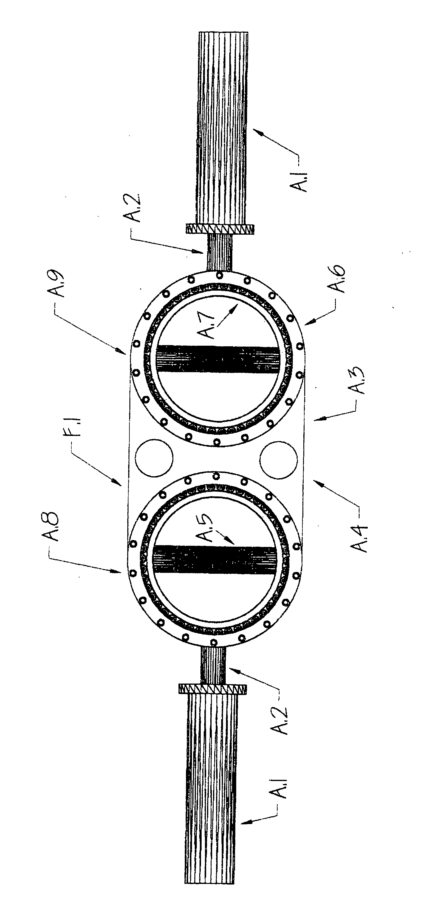
[0035] A preferred embodiment of the exercise bar of the present invention is illustrated in figure (1) front and rear views. The exercise bar is made entirely of carbon steel. The spacer (A.3) is one quarter inch thick and is lazer cut at each end of the spacer in a half circle the diameter of the outer ring (A.6) to provide a site for attaching the outer rings. The outer rings (A.6) are then welded to the spacer (A.3) at said site. Two one and one half inch diameter holes (A.4) are then drilled into the spacer (A.3) centered at the top and bottom of said spacer (A.3) to lighten the weight of the exercise bar. The two opposing ends of the exercise bar at the centerline of the exercise bar then have a one inch diameter, eight inch long cylindrical rod (A.2) welded to the centerline of the outboard outer ring (A.6), to provide a site for the attachment of a two inch outside diameter, seven and one half inch long cylindrical sleeve (A.1). The sleeve (A.1) pr...


PUM


Abstract

This invention is a weight lifting exercise bar with handle grip members selectively rotatable relative to the longitudinal axis of the exercise bar so that the exerciser can perform weight lifting exercises benefiting different muscle groups using a single exercise bar and a single set of weights. A set of ball bearings sandwitched between a pair of concentric rings, the outer ring being secured to exercise bar and the inner ring carrying the handle grip member. The inner ring member having the ability to smoothly rotate three hundred and sixty degree's, clockwise and or counterclockwise, independently of the outer ring member by the use of the ball bearings sandwitched between the inner ring member and the outer ring member. This invention allows for the handle grips to be rotated independently and freely while raising and lowering the exercise bar during it's intended use.

Description

BACKGROUND OF THE INVENTION [0001] 1. Field of Invention: [0002] The present invention relates to exercise equipment and more particularly to an improved exercise bar for weight lifting. [0003] 2. Background of the Invention [0004] The sport of weight lifting using exercise bars to lift weights is well known. In performing such lifting exercises, different bars may be used depending which set of muscle groups are being exercised during the lifting routine. For example, straight bars are used for general lifting, equal sets of weights being removabley secured near the outer ends of the bar, outboard of a gripping area. Curling bars are known to have a kink or bend in the bar in each of the two handle grip areas so that the exerciser's hands will be turned slightly relative to the axis of the bar during lifting. This increases the beneficial result to the bicep muscle. A tricep bar is known which has an even more pronounced bend in each handle grip portion so that exerciser's hands ar...

Claims


Application Information

Patent Timeline
Patent Type & Authority Applications(United States)
IPC IPC(8): A63B21/072A63B21/075
CPCA63B21/0724A63B2023/003A63B23/14A63B21/1434A63B21/4017
Inventor DE LANO, MICHAEL MARTIN
Owner DE LANO MICHAEL MARTIN
Learn More