
Adjustable spinal brace

a spinal brace and adjustable technology, applied in the field of adjustable spinal braces, can solve the problems of irritating trunk stiffness, unpleasant diffuse pressure on the trunk, and a lot of negative effects

Inactive Publication Date: 2005-09-15
CAMP SCANDINAVIA
View PDF3 Cites 14 Cited by
  • Summary
  • Abstract
  • Description
  • Claims
  • Application Information

AI Technical Summary

Benefits of technology

[0045] allowing a support in the optimal pain relieving level of the lumbar spine;
[0046] allowing a sufficient abdominal counterpressure to stabilize the device and keep the correct level of the lumbar lordosis, also to increase the intraabdominal pressure to decrease the intradiscal pressure (pain relieving effect);

Problems solved by technology

However, because of the rigidity of the brace, a lot of negative effects are seen such as an irritating stiffness of the trunk and unpleasant diffuse pressure on the trunk.
Furthermore, the pressure on the groins will negatively influence the mobility of the hips seen as difficulties to drive cars etc.
Other negative effects are excessive pressure of the upper border of the rigid brace on the thoracic cage, and the rigidity also makes movements of the arms more difficult.
The consequence of this is that, in spite of a clear pain relief when using the brace, the patients will not accept and use the brace.
It is known that the position of the spine giving a maximal pain relief is difficult to find.
This position for a maximal pain relief varies from one case to another, which means that a prefabricated shaped brace will not give the patient the maximal pain relief.
A problem with the prior art is that it is difficult to set the exact magnitude and position of the pressure by means of tightening straps.
As is mentioned above, another problem is that the abdominal and dorsal elements are large and encumber the movements of the body, e.g. lateral bending and movements of the arms and legs as well as sitting.
However, this test instrument is not suitable for day to day use because the design featured protruding screws and the like and was not generally designed for wearing under clothes.

Method used


Image

  • Adjustable spinal brace
  • Adjustable spinal brace
  • Adjustable spinal brace

Examples


Embodiment Construction

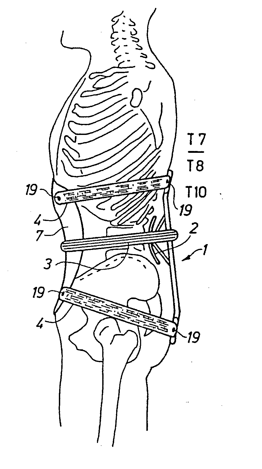
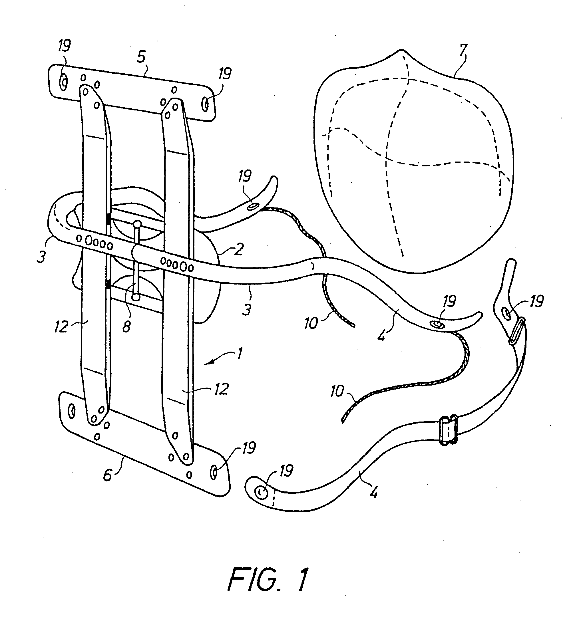
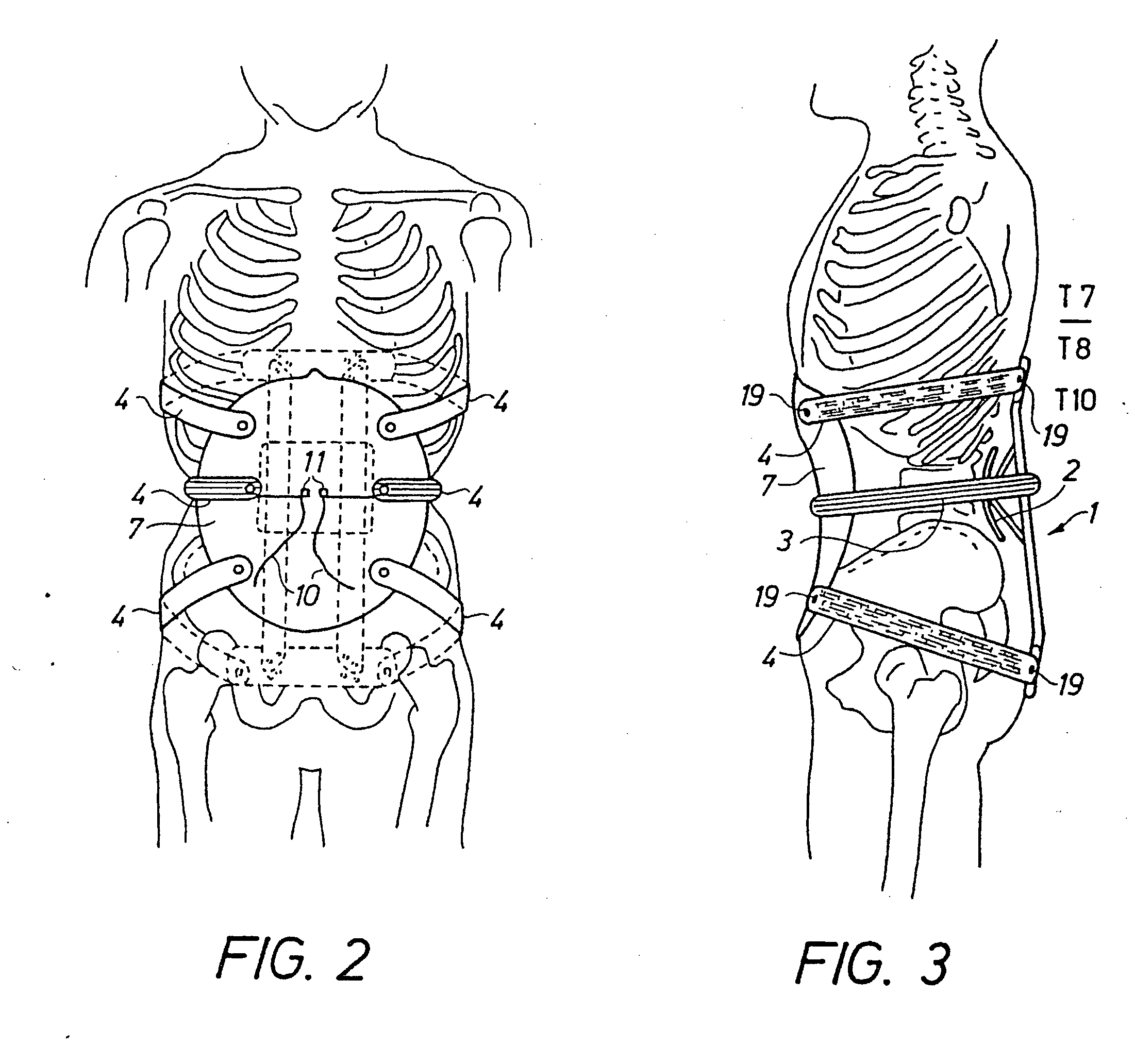
[0022] The invention provides an adjustable spinal brace, especially a lumbar brace, which is multi-adjustable for conservative treatment of low back pain. The pain may have various causes, such as discogenic hernia, spinal stenose, spondylotisthesis etc. The brace of the invention is a further development of the test instrument mentioned in the introduction, which is a tool to prove that conservative treatment could be effective. The present brace is designed for individual use during day and night. The design of the brace if virtually open at the lateral side, which allows for lateral bending. In general, the brace stabilises the spine in the sagittal plane.

[0023] One purpose of the brace is to stabilise the lumbar spine by the use of a “three point pressure” brace. Also, the brace restores lumbar lordosis to the individual needs by a multi-adjustable posterior lumbar pad.

[0024] A lightweight posterior frame bridges the lumbar spine from the distal end of the sacrum until the te...


PUM


Abstract

The invention relates to an adjustable spinal brace, which is multi-adjustable for conservative treatment of low back pain. The brace comprises an anterior abdominal pad and a posterior frame interconnected by a connection means. In accordance with the invention, the connection means comprises lateral iliac rolls to be positioned at the top of the pelvis bone (crista iliaca) and straps to be connected to the anterior abdominal pad. The posterior frame has a lumbar pad provided with pressure setting means for adjusting the applied pressure. The spinal brace is adjustable to enable an accurate magnitude and position of the pressure to correct the curvature of the spine, especially in the lumbar area. At the same time, the design of the brace is open at the lateral sides, which allows for lateral bending and normal movement of arms and legs.

Description

FIELD OF INVENTION [0001] The present invention relates to an adjustable spinal brace, and more particularly a lumbar brace, which is multi-adjustable for conservative treatment of low back pain. The spinal brace is adjustable to enable an accurate magnitude and position of the pressure to correct the curvature of the spine, especially in the lumbar area. At the same time, the design of the brace is open at the lateral sides, which allows for lateral bending and normal movement of arms and legs. STATE OF THE ART [0002] Various braces and other orthotic devices are known in the art. There are spinal braces with various heights, some intending to immobilise and stabilise the entire spine—thoracic as well as lumbar areas. Other types of spinal braces—low type—are only stabilising the lower part of the spine—the lumbar area. [0003] Furthermore, the rigidity of the brace varies a lot from soft braces made of fabrics to rigid braces made of plastics. The more rigid the brace is, the more ...

Claims


Application Information

Patent Timeline
IPC IPC(8): A61F5/01A61F5/02A61F5/03
CPCA61F5/024
Inventor WILLNER, STIGSMITS, JAN F.A.WILLNER, EVA
Owner CAMP SCANDINAVIA
Learn More