Surgical instrument for implants

a surgical instrument and implant technology, applied in the field of surgical instruments, can solve the problems of spinal deformity correction that cannot be adequately performed, neck, back, or peripheral nerve pain that can be chronic and sometimes debilitating, and may encounter difficulties in regard to the growth of incorporated bony material

Active Publication Date: 2005-09-15
AESCULAP IMPLANT SYST
View PDF18 Cites 88 Cited by
  • Summary
  • Abstract
  • Description
  • Claims
  • Application Information

AI Technical Summary

Problems solved by technology

This need is often the result of disease, damage or congenital deformation.
This condition results in chronic and sometimes debilitating neck, back, or peripheral nerve pain.
Quite often, spinal deformity correction cannot adequately be performed without interbody surgery.
The particular disadvantage of tube-shaped implants of this type, whereby two implants must be used between each two adjacent vertebrae in normal circumstances, is that the implants do not have a defined substantially flat support area on the vertebrate thus giving rise to the fear that difficulties will possibly be encountered in regard to the growth of the incorporated bony material.
This can result in implant subsidence and failure.
Biomechanically, these threaded devices can cause damage to the implants which compromise the stability of the construct.
However, there have been increasing reports of non-union when initially fusion was thought to have occurred and subsidence with sinking of the implants into the vertebral body.
Tapping causes destruction of the supportive end plates of the vertebrae allowing subsidence or “sinking in” of the implant into the body of the vertebrae.
This causes a loss of height of the spinal column with a narrowing of the foramina and a potential compression of the existing nerve root.
There is also a flattening of the lumbar lordosis resulting in lower back pain.
This in turn reduces the compressive strength of the implant.
This allows for impaction of the implant, but poor control of rotation, angulations, and does not allow for fine adjustments while the implant is being seated.
Another feature lacking in surgical instruments is the ability to remove the instruments in a way which will not encourage side loosening.
When an inserted instrument becomes jammed, lateral movement or force will tend to damage the surrounding areas.
The surgeon's lack of control over exit angle as well as entry angle is a problem in performing this type of procedure.
This is especially complicated by the fact that major blood vessels lie to either side of the operative area.
However, such implants are often designed for insertion only from one of the particular approaches of the spine.
Maintaining multiple implant designs may create inventory problems for both manufacturers and their customers.
Moreover, the complications of creating multiple implants to accomplish the same desired spacing is compounded when implants are made of a scarce resource, such as allograft bone.

Method used


Image

  • Surgical instrument for implants
  • Surgical instrument for implants
  • Surgical instrument for implants

Examples


second embodiment

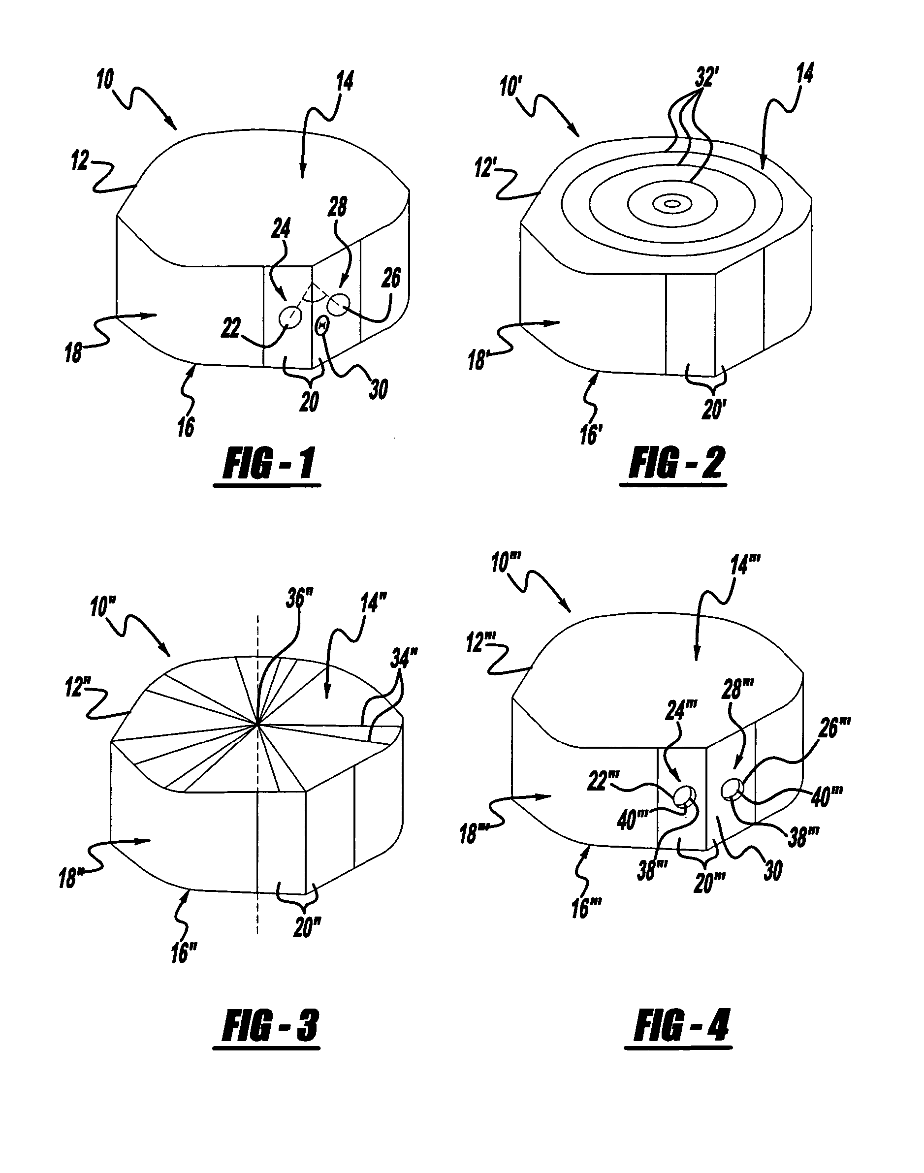
[0043] an implant used for insertion by the implant insertion device 60 of the present invention is a disk-shaped bone implant shown generally at 10′ in FIG. 2. The bone implant body 12′ includes a superior end face 14′ and an inferior end face 16′. An outer sidewall 18′ extend between the superior end face 14′ and the inferior end face 16′, and includes at least two flat sidewall portions, each indicated at 20′. The superior end face 14′ and the inferior end face 16′ each include concentric cuts 32′.

third embodiment

[0044] an implant used for insertion by the implant insertion device 60 of the present invention is a disk-shaped bone implant shown generally at 10″ in FIG. 3. The bone implant body 12″ includes a superior end face 14″ and an inferior end face 16″. An outer sidewall 18″ extend between the superior end face 14″ and the inferior end face 16″, and includes at least two flat sidewall portions, each indicated at 20″. The superior end face 14″ and the inferior end face 16″ each include radial cuts 34″ extending radially from the outer sidewall 18″ to a center 36″ of the implant body 12″.

fourth embodiment

[0045] an implant used for insertion by the implant insertion device 60 of the present invention is a disk-shaped bone implant shown generally at 10′″ in FIG. 4. A bone implant body 12′″ includes a superior end face 14′″ and an inferior end face 16′″. An outer sidewall 18′″ extends between the superior end face 14′″ and the inferior end face 16′″, and includes at least two flat sidewall portions, each indicated at 20′″. A first insertion pin hole 22′″ is included on a first flat sidewall portion 24′″, and a second insertion pin hole 26′″ is included on a second flat sidewall portion 28′″. A stress reliever in the form of a counter bore cut 38′″ is inside a distal end portion 40′″ of the pin holes 22′″ and 26′″ that relieves stress applied by a pin disposed in the pin hole.

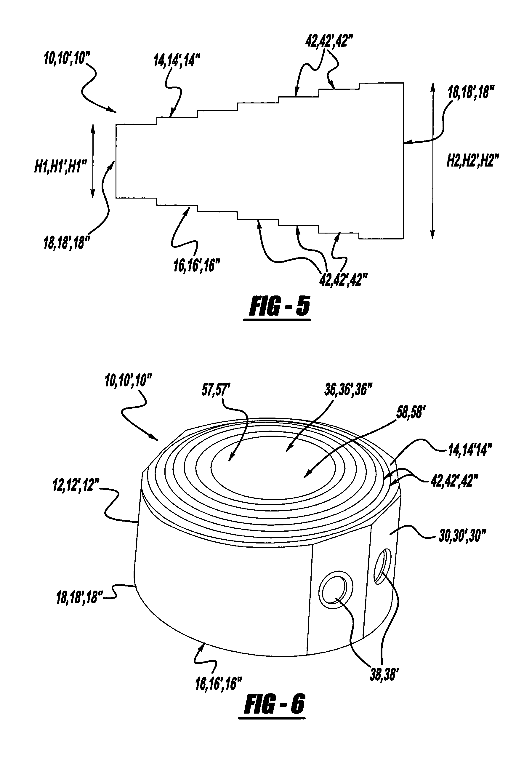
[0046] A method of forming a bone implant includes cutting concentric cuts 32, 32′, 32″ into the superior end face 14, 14′, 14″ and the inferior end face 16, 16′, 16″ of the bone implant 10, 10′, 10″. Another metho...


PUM


Abstract

An implant insertion device includes a handle, an insertion rod attached to the handle, and an implant gripper attached to the insertion rod. The implant gripper includes a gripping surface that has a movable pin and a fixed pin. The implant insertion device also includes a pin actuator so that the movable pin can be moved into place in an implant. A method of attaching an implant to an implant insertion device is disclosed, as well as a method of detaching an implant from an implant insertion device. Finally, a method of inserting an implant with an implant insertion device is provided.

Description

TECHNICAL FIELD [0001] The present invention relates to a surgical instrument for inserting bone implants between adjacent vertebral bodies of a spinal column. In particular, the present invention relates to an Anterior Lumber Interbody Fusion bone implant insertion device that can be used to insert a bone implant from both a straight anterior direction and an oblique lateral direction. BACKGROUND [0002] In various orthopedic surgical procedures, it is necessary to secure portions of a spinal column in a relatively fixed relationship. This need is often the result of disease, damage or congenital deformation. For example, when one or more intervertebral disks of the spine degenerate due to trauma or disease, the spinal cord or emergent nerve can become compressed. This condition results in chronic and sometimes debilitating neck, back, or peripheral nerve pain. It has become increasingly recognized that fusion between two adjacent vertebral bodies in the space occupied by the implan...

Claims


Application Information

Patent Timeline
Patent Type & Authority Applications(United States)
IPC IPC(8): A61B17/58A61F2/00A61F2/28A61F2/30A61F2/44A61F2/46
CPCA61F2/28A61F2/30771A61F2/44A61F2/4455A61F2/4611A61F2002/30224A61F2310/00359A61F2002/30331A61F2002/30601A61F2002/3082A61F2002/4627A61F2220/0033A61F2230/0069A61F2002/30233
Inventor LO, JANZENWANG, JEFFREY C.RYSHKUS, CHAD E.
Owner AESCULAP IMPLANT SYST
Why Eureka
Try Eureka