Deterministic packet marking

a packet marking and deterministic technology, applied in the field of methods, can solve the problems of inability to trace back to slaves by other existing schemes, limited involvement of internet service providers (isps), and minimal changes to the infrastructure and operation required for deployment of dpm

Inactive Publication Date: 2005-09-15
NEW JERSEY INSTITUTE OF TECHNOLOGY
View PDF6 Cites 6 Cited by
  • Summary
  • Abstract
  • Description
  • Claims
  • Application Information

AI Technical Summary

Problems solved by technology

Tracing back to the slaves cannot be done by other existing schemes.
The involvement of the Internet Service Providers (ISPs) is very limited, and changes to the infrastructure and operation required to deploy DPM are minimal.

Method used


Image

  • Deterministic packet marking
  • Deterministic packet marking
  • Deterministic packet marking

Examples


Embodiment Construction

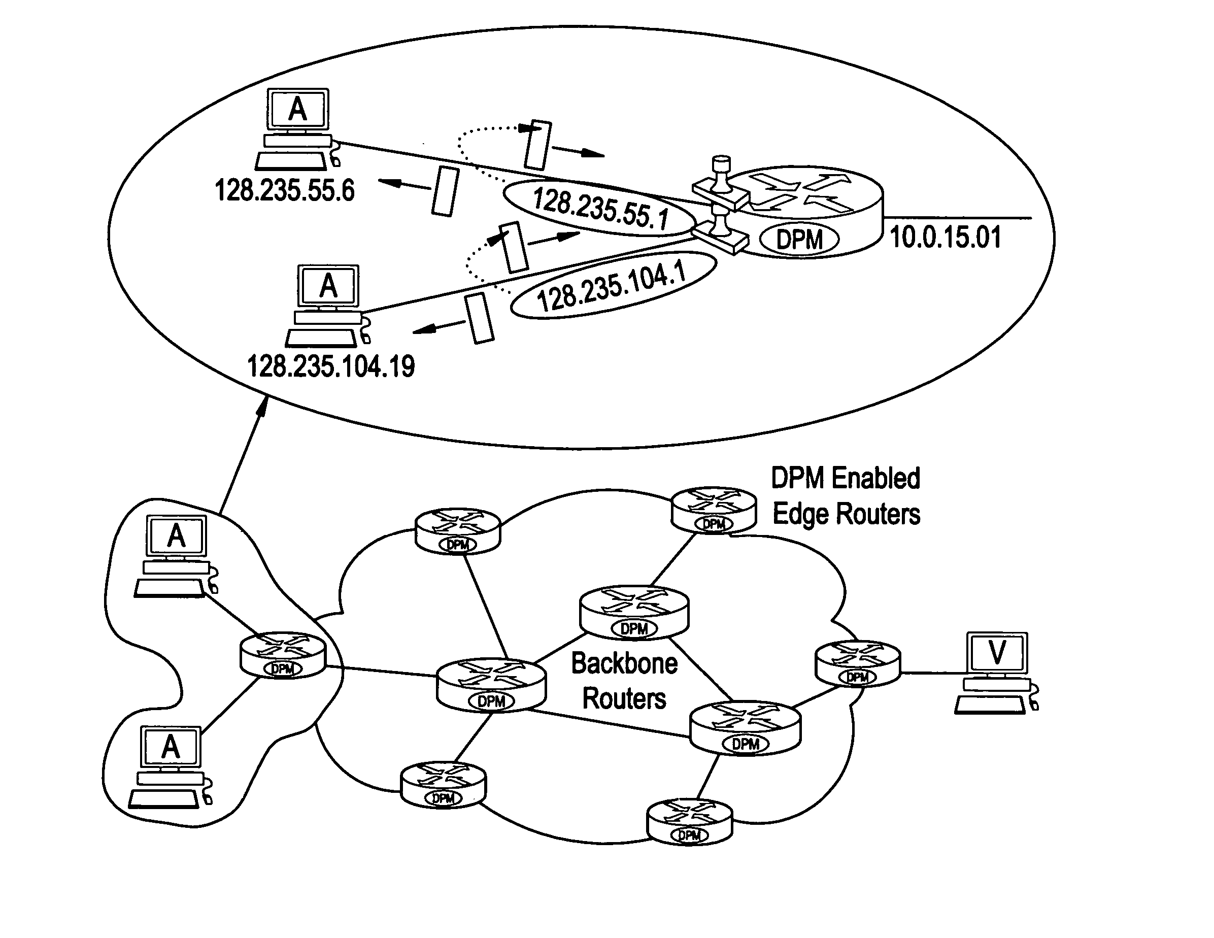
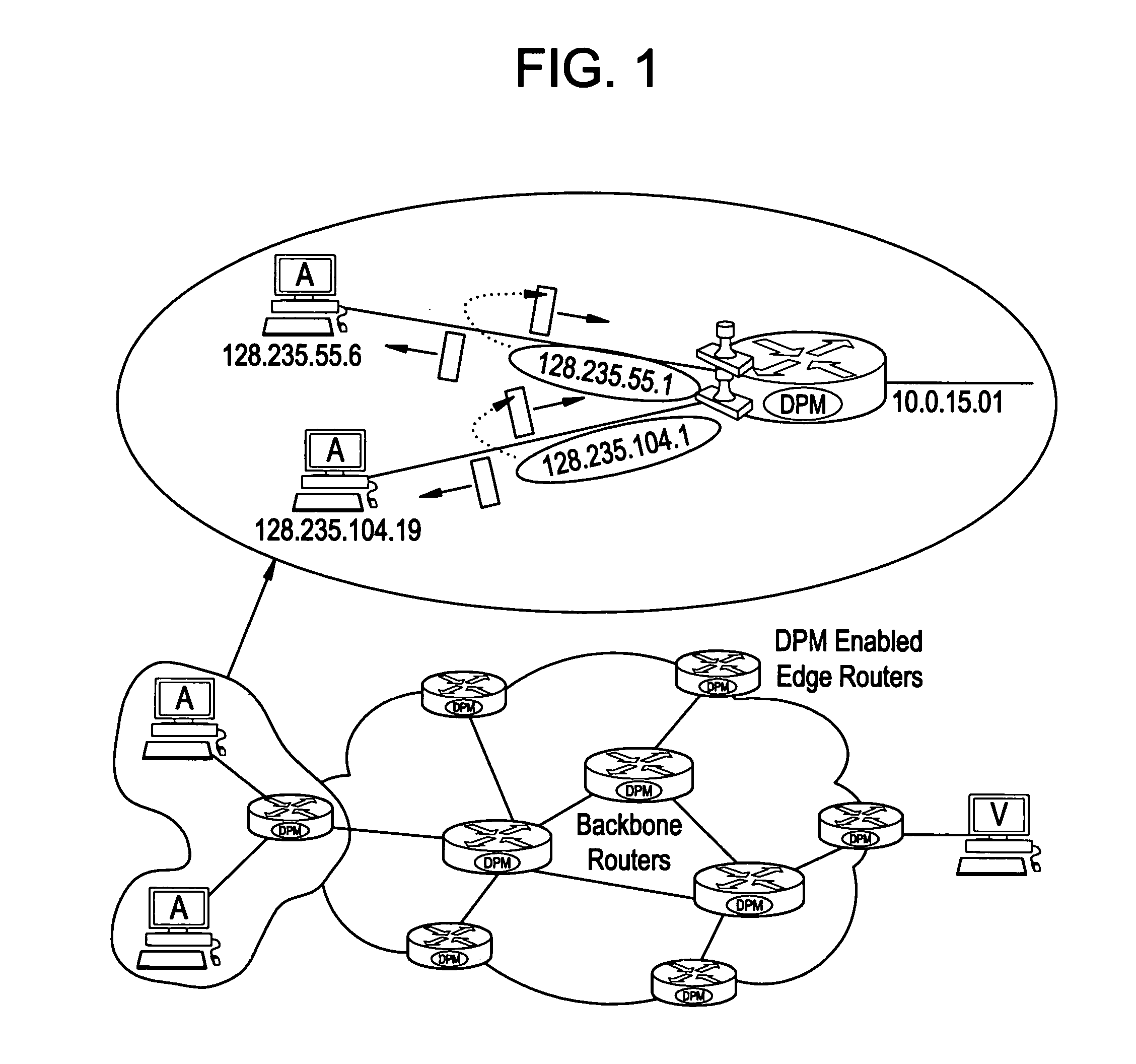
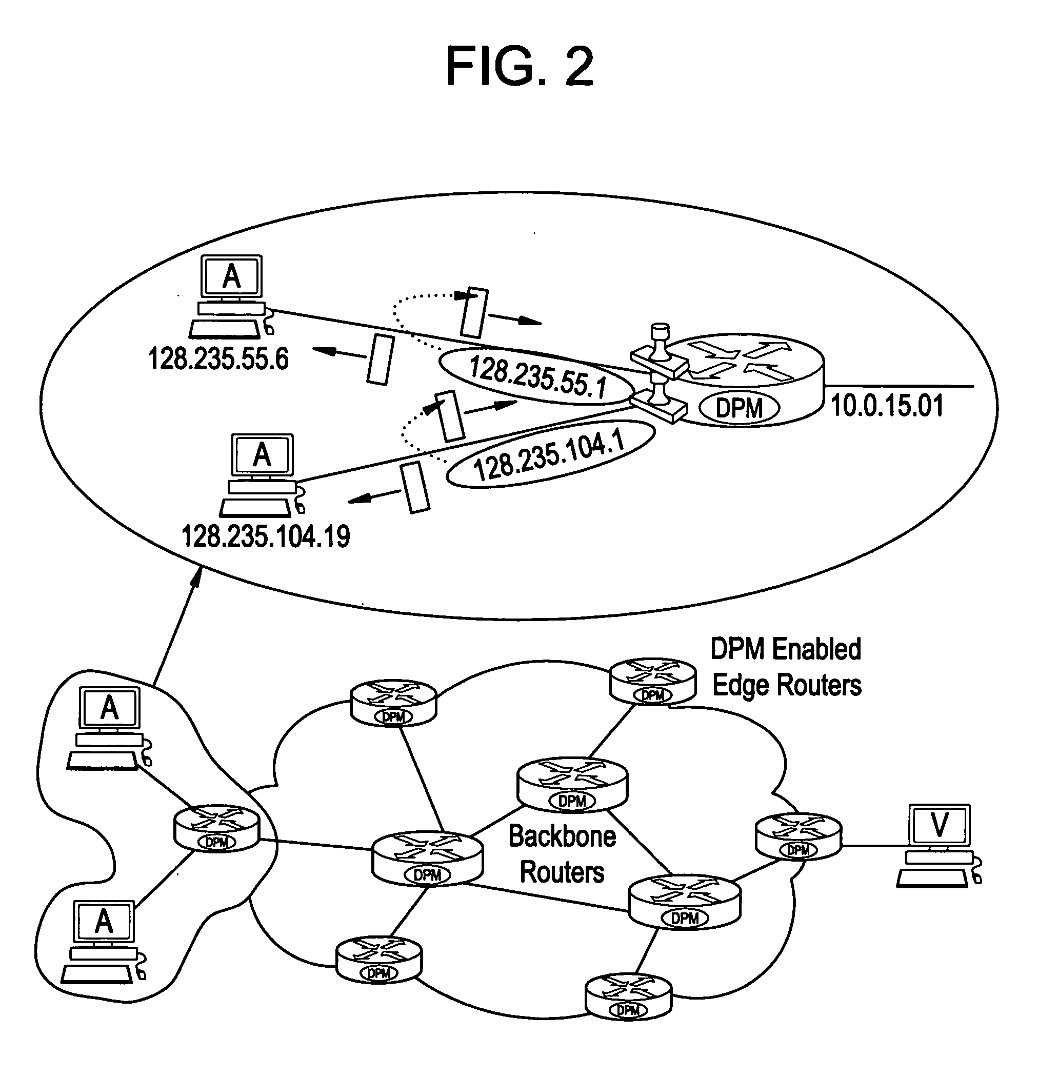
[0017] The basic DPM is a packet marking algorithm. We first consider the general principle behind DPM and discusses the most basic implementation of the scheme.

[0018] By “Deterministic Packet Marking” we refer to the fact that every packet traversing a DPM-enabled router is marked, i.e., the packet is inscribed with partial information of the router interface, as opposed to “Probabilistic Packet Marking” in which each packet is marked by a router along the traversed path with a probability, say, 0.04 (4%), i.e., some packets may not be marked at all.

[0019] The two key assumptions applicable to the method are (1) that an attacker may generate any packet; and (2) that routers are both CPU and memory limited.

[0020] The 16-bit packet Identification (ID) field and 1-bit Reserved Flag (RF) in the IP header are used to mark packets. Each packet is marked when it enters the network. This mark remains unchanged for as long as the packet traverses the network. This automatically removes t...


PUM


Abstract

The deterministic packet marking (DPM) method is based on marking packets with the partial address information of ingress interface only. The attack victim is able to recover the complete address(es) information after receiving several packets from a particular attacking host or hosts. The full path is not really essential for the traceback since it can be different for different packets for different reasons.

Description

RELATED APPLICATIONS [0001] This application claims priority from U.S. Provisional patent Applications Ser. No. 60 / 552,645, filed Mar. 12, 2004; Ser. No. 60 / 552,647 filed Mar. 12, 2004, and 60 / 553,212 filed Mar. 15, 2004.FIELD OF INVENTION [0002] This invention relates generally to methodology useful in securing the Internet infrastructure, and more specifically relates to methods for tracing internet attacks back to their source or sources. BACKGROUND OF INVENTION [0003] In recent years, much interest and consideration has been paid to the topic of securing the Internet infrastructure that continues to become a medium for a broad range of transactions. A number of approaches to security have been proposed, each attempting to mitigate a specific set of concerns. The specific threat, which is the main focus of this application, is anonymous attacks. In anonymous attacks, the identity of the attacker(s) is not immediately available to the victim since the Source Address (SA) field in ...

Claims


Application Information

Patent Timeline
Patent Type & Authority Applications(United States)
IPC IPC(8): H04L69/40
CPCH04L63/1441H04L63/126
Inventor BELENKY, ANDREYANSARI, NIRWAN
Owner NEW JERSEY INSTITUTE OF TECHNOLOGY
Why Eureka
Try Eureka