Insulated structural building panel and assembly system

a technology of structural building panels and assembly systems, applied in the direction of girders, joists, trusses, etc., can solve the problems of design lack of thermal break between each pair of metal studs, high cost, additional tooling, etc., and achieve the effect of easy cutting to the width

Inactive Publication Date: 2005-09-22
RUE JERRY RANDALL
View PDF22 Cites 103 Cited by
  • Summary
  • Abstract
  • Description
  • Claims
  • Application Information

AI Technical Summary

Benefits of technology

[0016] In another aspect, a panel track formed as a channel section is provided that includes a plurality of holes disposed along each respective first and second edge of the first side of the panel track for receiving fasteners to secure the panel track to a foundation surface or to a pair of L-shaped headers inverted over the upper end of a wall panel cap. The steel panel track may be used in combination with the L-shaped headers to support window and door in-fill caps, securely integrating the in-fill caps with the adjoining wall panels to provide a solid, full-strength wall.

Problems solved by technology

However, the conventional foam / steel building panels are characterized by several significant inefficiencies in the manufacture of the panels and the construction of buildings that results in relatively high costs as compared to ordinary wood frame “stick built” construction.
As in the previous example, this prior art example requires a distinct manufacturing step involving additional tooling, set-up and material costs.
Moreover, this design lacks a thermal break between each pair of metal studs.
Inefficiencies further result from the methods employed to secure the steel framing members to the EPS foam body of the panels.
Moreover, since most buildings are generally different from each other in many respects, the standard panels must be cut to size or shape to fit a particular application, which is a labor-intensive and expensive task if conventional tools are used.
Alternatively, the panel parts may be prefabricated at the place of manufacture to submitted detail drawings, which is also time consuming and expensive, and generally involves costly tooling and set-up charges.
The effect of all of these cost factors substantially limits the marketability of these highly thermal efficient building panels for all but uncomplicated, standardized structures.

Method used


Image

  • Insulated structural building panel and assembly system
  • Insulated structural building panel and assembly system
  • Insulated structural building panel and assembly system

Examples


Embodiment Construction

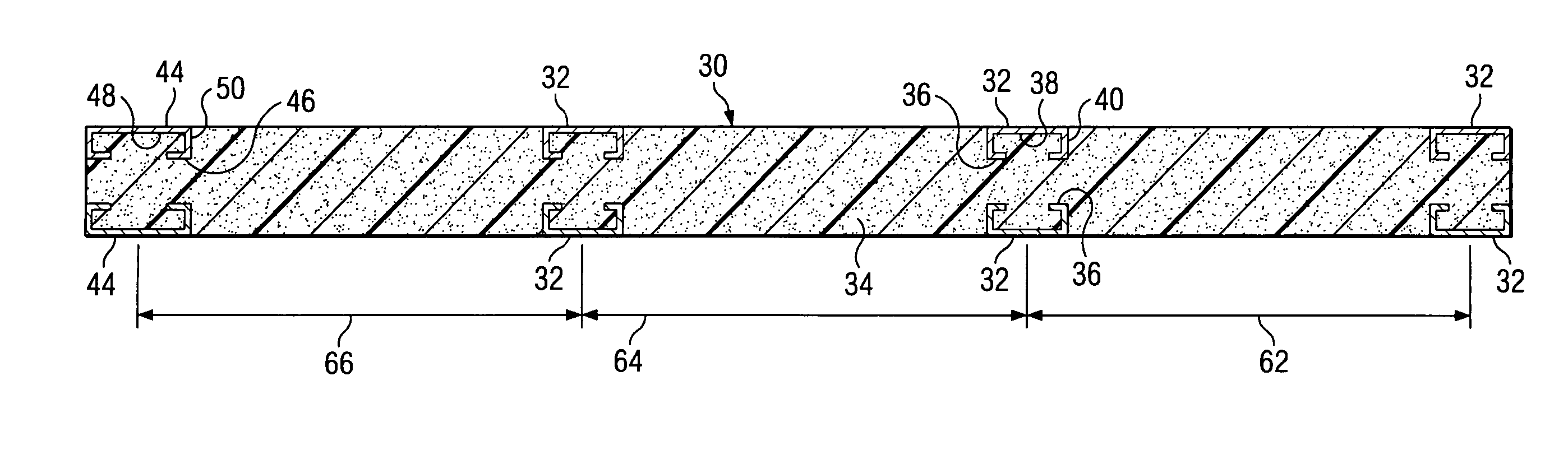
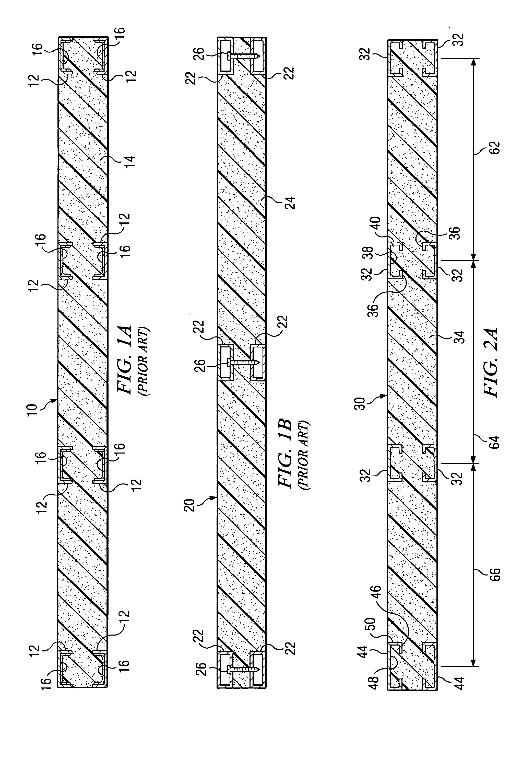
[0050] Referring to FIG. 2A, there is illustrated a simplified cross section through the width of one embodiment of an improved insulated building panel, i.e., an insulated structural building (“ISB”) panel 30 according to the present disclosure. The ISB panel 30 shown in FIG. 2A has a panel body 34 that is illustratively approximately 4.00 inches thick and 48 inches wide. The ISB panel 30 further has embedded framing members 32, 44 that have an inward-directed “return” lip 36, 46 respectively disposed along each edge of each of the channel-shaped framing members 32, 44. The purpose of the return lip 36, 46 (identified on only one of each type of framing member 32, 44) is to retain the framing member 32, 44 in the rigid foam panel body 34 of the ISB panel 30 without adhesives or mechanical or other fasteners. It will be appreciated that the return lips 36, 46 are preferably directed inward toward each other in ISB panels having framing members disposed along the edges of the panel b...


PUM

PropertyMeasurementUnit
densityaaaaaaaaaa
tensile strengthaaaaaaaaaa
distanceaaaaaaaaaa

Abstract

An insulated structural building panel and header system, comprising a rectangular panel body molded of a rigid foam material and a plurality of elongated, channel-shaped framing members oriented parallel to each other and embedded during molding in each first and second face of the panel body. Each framing member is retained in place in the panel body by return lips formed into first and second edges of an open side of the framing members without the use of adhesive or mechanical fasteners. The panels may include utility recesses formed in one face of the panel and mortised edges for keying the panels securely together. The panels may be formed with alternate framing member spacings. Auxiliary framing members are disclosed having T and L shaped cross sections for joining panels together or reinforcing the panels to support greater loads.

Description

CROSS REFERENCE [0001] The present U.S. patent application claims priority from earlier filed U.S. Provisional Patent Applications Ser. No. 60 / 549,587 filed Mar. 3, 2004 and entitled “Improved Foam Insulated Building Panel And System,” and Ser. No. 60 / 555,985 filed Mar. 24, 2004 and entitled “Foam Insulated Building Panel And Utility System.”BACKGROUND OF THE INVENTION [0002] 1. Field of the Invention [0003] The present invention generally relates to insulated structural building panels and, more particularly, to advances in the design of the building panels enabling significantly reduced costs of manufacturing the panels and of constructing buildings using the panels. [0004] 2. Background of the Invention [0005] Insulated building panels having both structural and insulating properties have long been available in several forms. Among the better known types are structural insulated panels (“SIP”), which typically comprise a solid core of insulating material, such as expanded polysty...

Claims


Application Information

Patent Timeline
Patent Type & Authority Applications(United States)
IPC IPC(8): E04B1/00E04B1/14E04B1/61E04B5/02E04C1/00E04C2/22E04C2/32E04C2/38E04C3/04E04C3/09
CPCE04B1/0023E04B1/14E04B1/6116E04B1/6145E04B5/02E04C2003/0491E04C2/322E04C2/384E04C3/09E04C2003/0413E04C2/22
Inventor RUE, JERRY RANDALL
Owner RUE JERRY RANDALL
Why Eureka
Try Eureka