Building change detection method based on density of projection points of movable window

A technology of moving window and change detection, which is applied in the direction of measuring devices, instruments, and optical devices, etc., can solve the problems of insufficient accuracy of change detection methods, poor earthquake resistance, and unclear targets.

Active Publication Date: 2016-11-09
HOHAI UNIV
View PDF5 Cites 22 Cited by
  • Summary
  • Abstract
  • Description
  • Claims
  • Application Information

AI Technical Summary

Problems solved by technology

[0002] In cities, buildings are the main places for human activities, and their safety status is related to human daily life and economic activities. Therefore, it is of great significance to detect changes in buildings. Based on the change detection and repair of buildings, especially The deformation and damage of buildings caused by earthquakes has been the focus of research in the industry in recent years. In the development history of building structures, masonry structures have been widely used in the foundation structure of buildings since ancient times. Bricks, stones, masonry And adobe and other blocks, a combination of mortar (mortar, clay slurry, etc.) However, its masonry strength is low and its earthquake resistance is poor. Therefore, the research on change detection of masonry buildings ha

Method used


Image

  • Building change detection method based on density of projection points of movable window
  • Building change detection method based on density of projection points of movable window
  • Building change detection method based on density of projection points of movable window

Examples


Embodiment Construction

[0059] The technical solution of the present invention will be described in detail below, but the protection scope of the present invention is not limited to the embodiments.

[0060] Such as figure 1 As shown, a building change detection method based on the projection point density of a moving window includes the following steps:

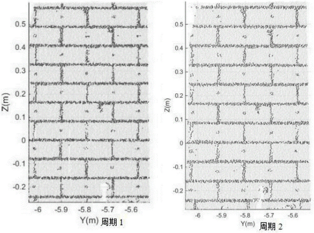
[0061] (1) A laser scanner system is used to scan the same building in two phases to obtain point cloud data on the surface of the building. Set m targets in a fixed area around the changing building. Generally, m≥4, considering the laser scanner It comes with an automatic leveling function, and the instrument is in a horizontal state during each measurement. Therefore, m≥3. The observation value of the laser scanner system is the three-dimensional coordinates of the building surface point and the laser reflection intensity;

[0062] (2) Use the target set in step (1) to calculate the two-phase point cloud coordinate conversion parameter Z to register th...


PUM


Abstract

The invention discloses a building change detection method based on the density of projection points of a movable window. The method comprises the steps that two periods of point cloud data are collected and registered; dimension-reducing analysis is carried out on a fixed wall; projection points of a station point in a plane of the fixed wall are calculated, and a structural coordinate system is established; the two periods of point cloud data are transformed to the structural coordinate system; a k-means classification method is used to obtain a brick point cloud and a mortar point cloud; the mortar point cloud is projected to the direction Z and the direction Y; a fixed window length Lfix and a movable window length Lmove are defined, and point-cloud linear density change along the direction Z and the direction Y is calculated; horizontal and vertical segmentation lines among bricks are calculated, coordinates of four corners of each brick and the center of each brick are calculated; and change is detected by utilizing the centers of the corresponding brick in two periods. According to the invention, deformation information of the centers of the bricks of the wall is extracted automatically, the automation degree is improved greatly, original data is mined fully, and it is ensured that deformation information of the bricks of a brick-structured building can be obtained effectively on the premise that the precision is ensured.

Description

Technical field [0001] The invention designs a building change detection method, in particular to a building change detection method based on a moving window. Background technique [0002] In cities, buildings are the main places for human activities, and their safety status is related to human daily life and economic activities. Therefore, the change detection of buildings is of great significance. Based on the change detection and repair of buildings, especially The deformation and damage of buildings caused by earthquakes has been the focus of research in the industry in recent years. In the history of the development of building structures, masonry structures have been widely used in building foundation structures since ancient times, using bricks, stones, and masonry. A combination of various blocks such as adobe and mortar (mortar, clay slurry, etc.) is a masonry structure. The masonry structure is widely used due to its low cost, fire resistance, durability and ease of con...

Claims


Application Information

Patent Timeline
IPC IPC(8): G01B11/16
CPCG01B11/16
Inventor 沈月千黄腾王伟沈哲辉高鹏韩易李成仁
Owner HOHAI UNIV
Why Eureka
Try Eureka