Drying apparatus

a drying apparatus and drying technology, applied in the field of drying apparatuses, can solve the problems of miniaturizing such a drying apparatus, shortening the time required to dry clothes, and wasting energy

Inactive Publication Date: 2005-09-22
PANASONIC CORP
View PDF10 Cites 54 Cited by
  • Summary
  • Abstract
  • Description
  • Claims
  • Application Information

AI Technical Summary

Benefits of technology

[0024] According to a fourteenth aspect of the invention, in the drying apparatus of any one of the first, fifth or eleventh aspect, the heat pump apparatus sets the temperature of the refrigerant run into the radiator to the temperature of boiling water or more.
[0025] According to a fifteenth aspect of the invention, in the drying apparatus of any one of the first, fifth or eleventh aspect, the heat pump apparat...

Problems solved by technology

Since the quantity of heat has a limitation due to a current capacity of an outlet for home use, it becomes an obstacle to shorten the time required to dry clothes.
Further, since the heat used to dry the clothes is discharged to the outside thereof without reuse, there is wasted energy.
Thus, since many components are required in comparison with a drying apparatus in which an electric heater is used and such a drying apparatus has a large size, there is a problem to miniaturize s...

Method used


Image

  • Drying apparatus
  • Drying apparatus
  • Drying apparatus

Examples


first embodiment

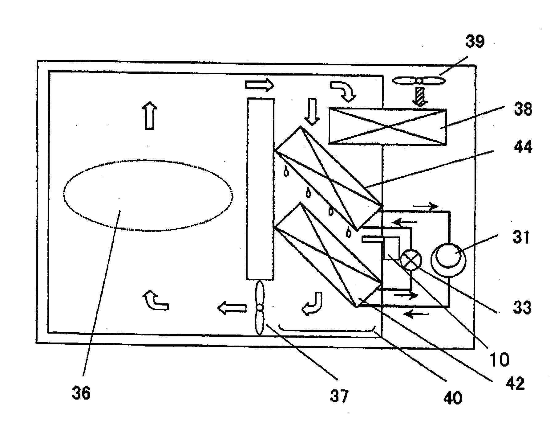
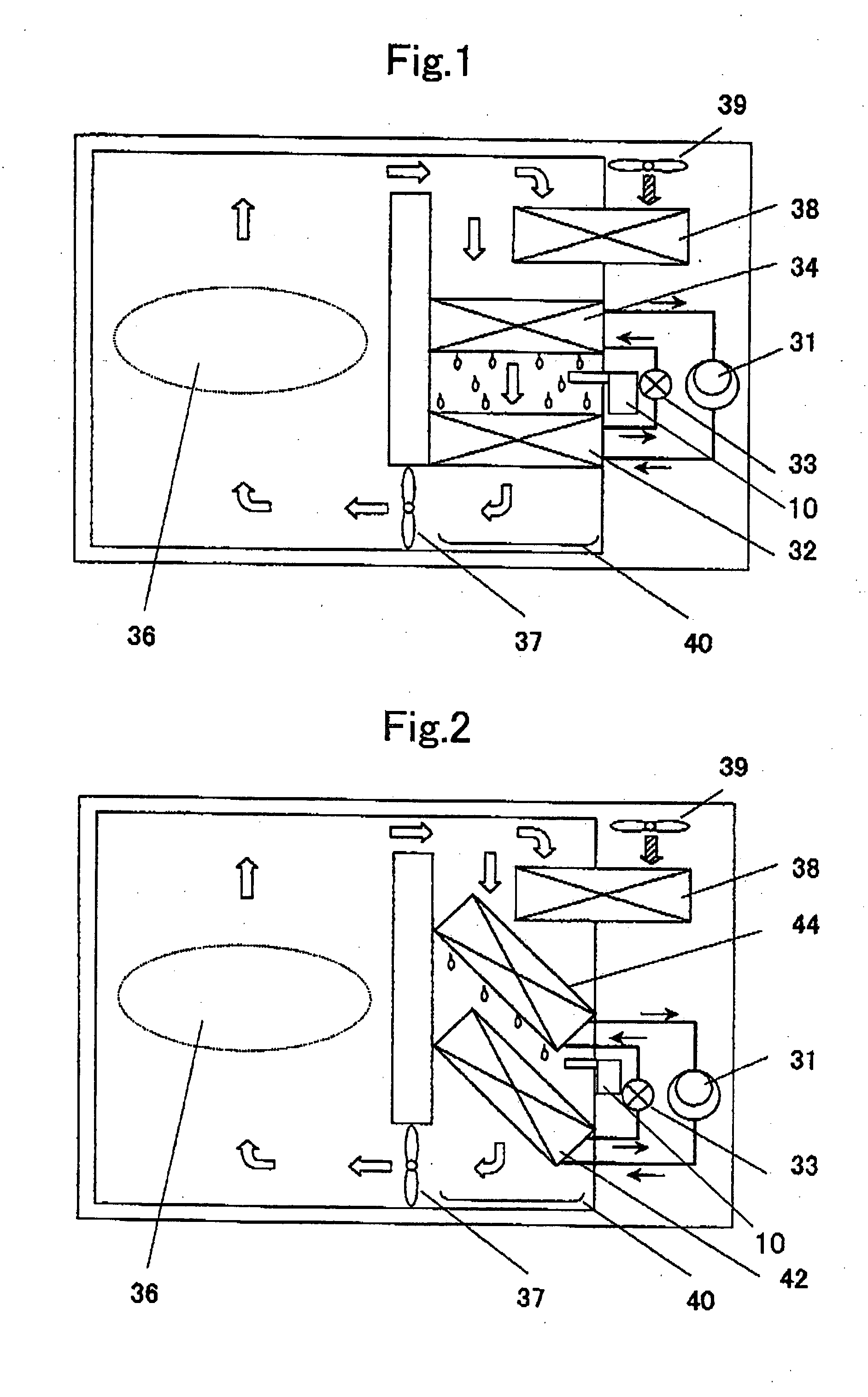
[0045]FIG. 1 is a block diagram of a drying apparatus according to a first embodiment of the present invention. Referring to FIG. 1, a reference number 31 represents a compressor, a reference number 32 represents a radiator, a reference number 33 represents an expansion valve (expansion mechanism), and a reference number 34 represents an evaporator. A heat pump apparatus is constructed by connecting these constituent elements to one another in this order through pipes and charging a refrigerant thereinto. As the refrigerant, a refrigerant which can be brought into the supercritical state on the radiation side (from a discharge section of the compressor 31, to the radiator 32 and to an inset section of the expansion mechanism 33) such as a CO2 refrigerant is charged thereinto. A reference number 36 represents a subject to be dried (for example, clothes, a bathroom space, or the like), a reference number 37 represents a blower fan, a reference number 38 represents a heat exchanger for...

second embodiment

[0055] Hereinafter, a second embodiment of the present invention will now be described with reference to the drawings.

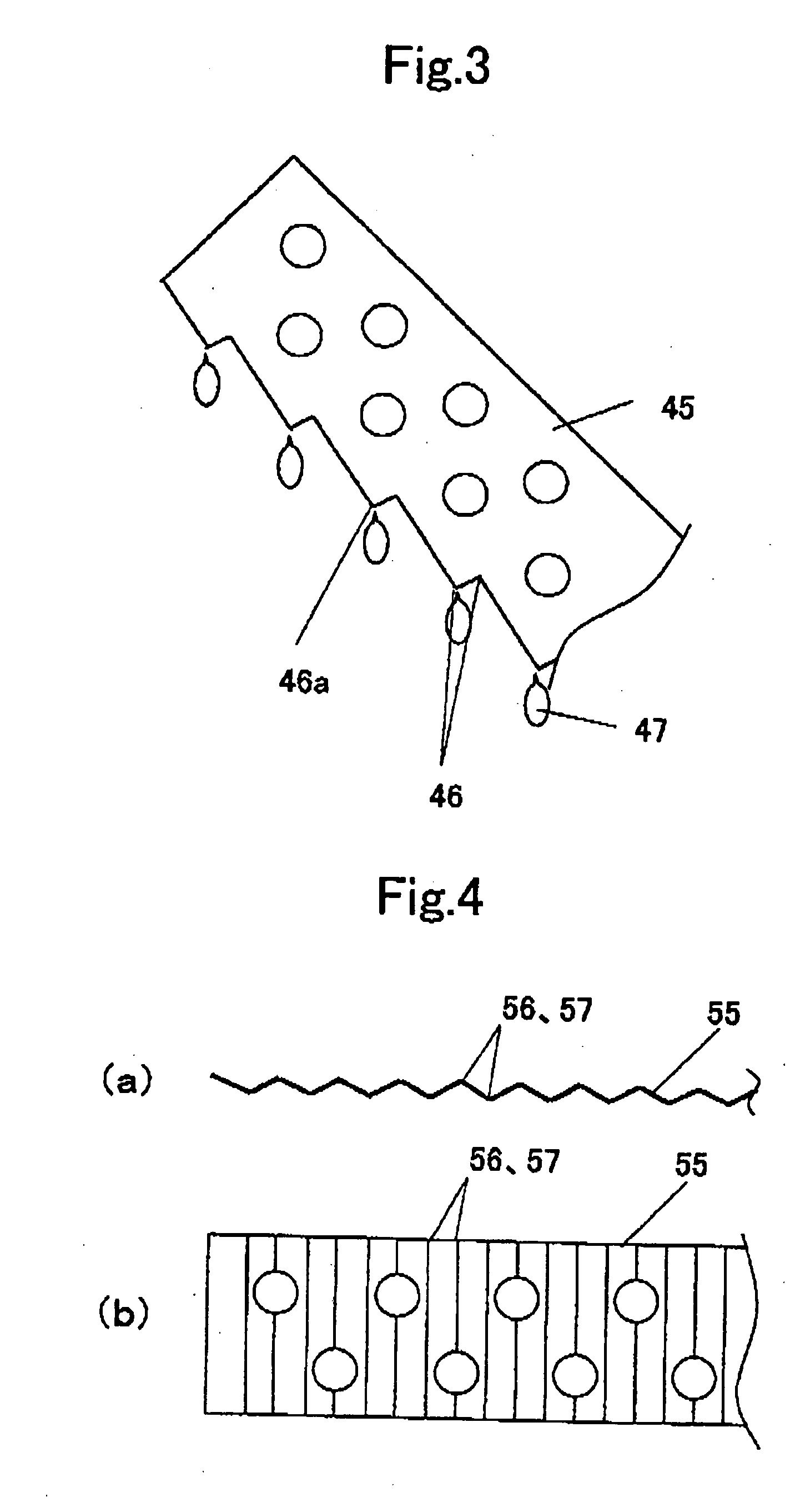
[0056]FIG. 2 is a block diagram of a drying apparatus according to a second embodiment of the present invention. FIG. 3 is an enlarged view of a main portion of a fin constituting an evaporator according to the second embodiment of the present invention. In FIG. 2, common constituent elements shown in FIG. 1 are designated with the same reference numbers, and explanation thereof will be omitted. A reference number 31 represents a compressor, a reference number 42 represents a radiator, a reference number 33 represents an expansion valve (expansion mechanism), and a reference number 44 represents an evaporator. A heat pump apparatus is constructed by connecting these constituent elements to one another in this order through pipes and charging a refrigerant thereinto. As the refrigerant, a CO2 refrigerant which can be brought into the supercritical state on the radiat...

third embodiment

[0063] Hereinafter, a third embodiment of the present invention will now be described with reference to the drawing.

[0064]FIG. 5 is a block diagram of a drying apparatus according to a third embodiment of the present invention. In FIG. 5, common constituent elements shown in FIG. 1 are designated with the same reference numbers, and explanation thereof will be omitted. A reference number 31 represents a compressor, a reference number 62 represents a radiator, a reference number 33 represents an expansion valve (expansion mechanism), and a reference number 64 represents an evaporator. A heat pump apparatus is constructed by connecting these constituent elements to one another in this order through pipes and charging a refrigerant thereinto. As the refrigerant, a CO2 refrigerant which can be brought into the supercritical state on the radiation side is charged thereinto. Difference between the first and third embodiments is a point that drain water condensed and generated by dehumidi...


PUM


Abstract

A drying apparatus has a heat pump apparatus having a compressor, a radiator, an expansion mechanism and an evaporator connected in this order via pipes through which a refrigerant is circulated. The drying apparatus has a structure in which drying air heated in the radiator is introduced into a subject to be dried, drying air obtained by removing moisture or water from the subject to be dried is cooled and dehumidified by the evaporator, and then the drying air is reheated in the radiator to be reused as renewed drying air. The drying apparatus also has a structure in which drain water generated by dehumidifying the drying air in the evaporator is dropped or sprayed into the radiator.

Description

TECHNICAL FIELD [0001] The present invention relates to a drying apparatus with a heat pump apparatus that is constructed by circularly connecting a compressor, a radiator, a throttle apparatus and an evaporator. BACKGROUND OF THE INVENTION [0002] In an electric type cloth drier used in a general household, the quantity of heat required to dry clothes is converted from electric energy with an electric heater. Since the quantity of heat has a limitation due to a current capacity of an outlet for home use, it becomes an obstacle to shorten the time required to dry clothes. Further, since the heat used to dry the clothes is discharged to the outside thereof without reuse, there is wasted energy. [0003] As for a conventional cloth drier, a low-power cloth drier with high dehumidification efficiency in which a heat pump apparatus is used as a heat source for drying clothes and a part of drying air is discharged to the outside thereof has been proposed (for example, see Japanese Patent Ap...

Claims


Application Information

Patent Timeline
IPC IPC(8): D06F58/02D06F58/10D06F58/20D06F58/24F24F1/00F24F3/153F24F13/22F25B1/00F25B9/00F25B30/02F26B9/06F26B21/04F28F1/30
CPCD06F58/206D06F58/24F26B21/086F25B9/008F25B2309/061F24F3/153
Inventor NISHIWAKI, FUMITOSHIYAKUMARU, YUUICHITAMURA, TOMOICHIRO
Owner PANASONIC CORP
Why Eureka
Try Eureka