Drill adapter for an ice auger

a technology of drill adapter and ice auger, which is applied in the field of ice augers, can solve the problems of not being useful to other individuals, requiring a separate dedicated motor, and requiring a great amount of strength and energy to drill through a thick layer of ice using a hand-powered ice auger, so as to achieve the effect of reducing vibration and being easy to repla

Inactive Publication Date: 2005-09-22
KOLLASCH JASON E +3
View PDF13 Cites 17 Cited by
  • Summary
  • Abstract
  • Description
  • Claims
  • Application Information

AI Technical Summary

Benefits of technology

[0013] It is another object of the invention to provide a drill adapter for an ice auger that has a floating shield, which has a diameter larger than that of the cutting diameter of the auger to thereby prevent the auger from falling through the hole it produces.
[0014] It is a further object of the invention to provide a drill adapter for an ice auger that incorporates a spring to help minimize vibration and thereby act as a shock absorber.
[0015] Still another object of the invention is to provide a drill adapter for an ice auger that incorporates a removable driver bit that can be easily replaced if damaged.
[0016] It is an object of the invention to provide improved elements and arrangements thereof for the purposes described which presents safety features and is inexpensive, dependable and fully effective in accomplishing its intended purposes.

Problems solved by technology

However, boring a hole through a thick layer of ice using a hand-powered ice auger required a great expenditure of strength and energy.
; and U.S. Pat. No. 6,076,617, issued Jun. 20, 2000 to J. M. Berner, teach motorized augers, but each of these devices requires the expense of a separate dedicated motor.
Although useful for those individuals possessing a chainsaw or grass-trimming tool, these devices are not useful for other individuals.
However, each of these has several drawbacks.
First, while each includes a safety shield to prevent the auger from falling through the hole produced by the auger, the shield is attached to the adapter such that it spins with the adapter and therefore presents a potential safety hazard should the shield contact clothing or the operator when drilling.
Second, each includes a permanently integrated driver bit that cannot be easily replaced if bent or broken.

Method used


Image

  • Drill adapter for an ice auger
  • Drill adapter for an ice auger
  • Drill adapter for an ice auger

Examples


Embodiment Construction

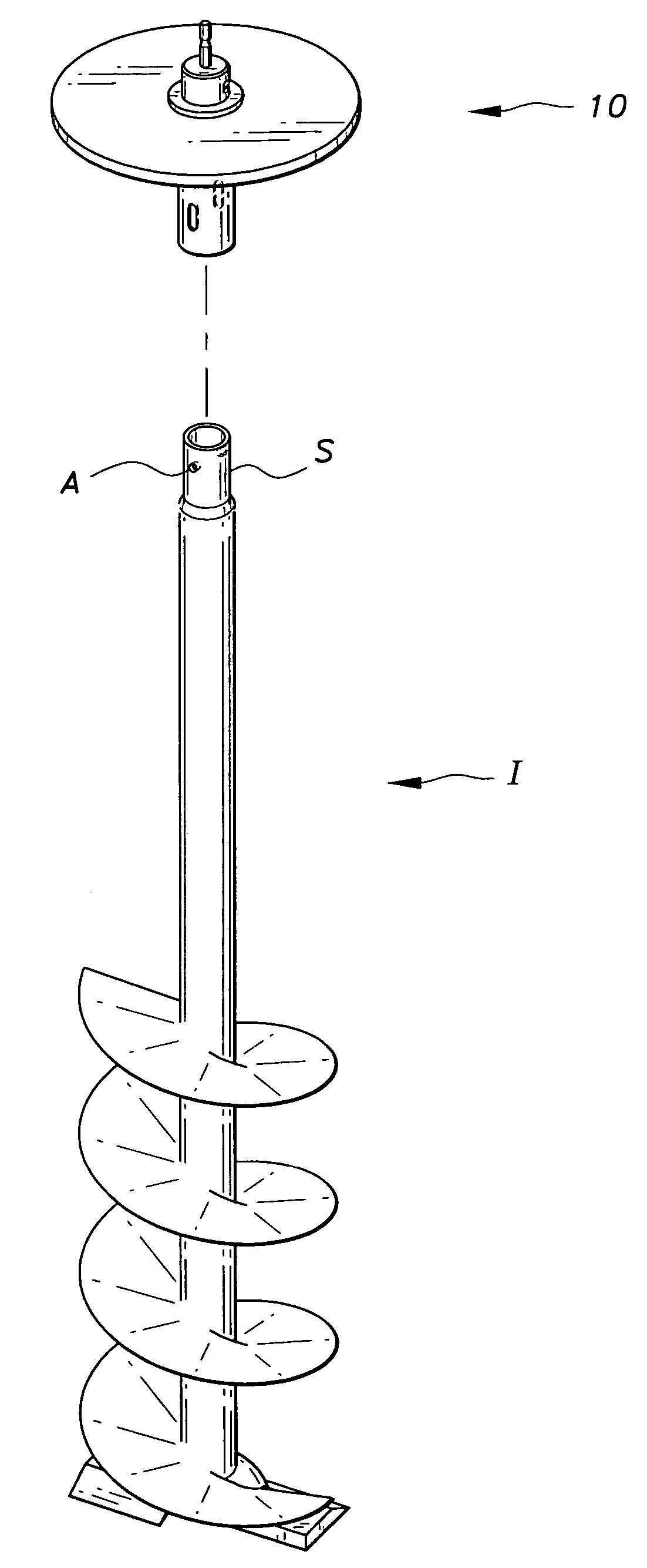
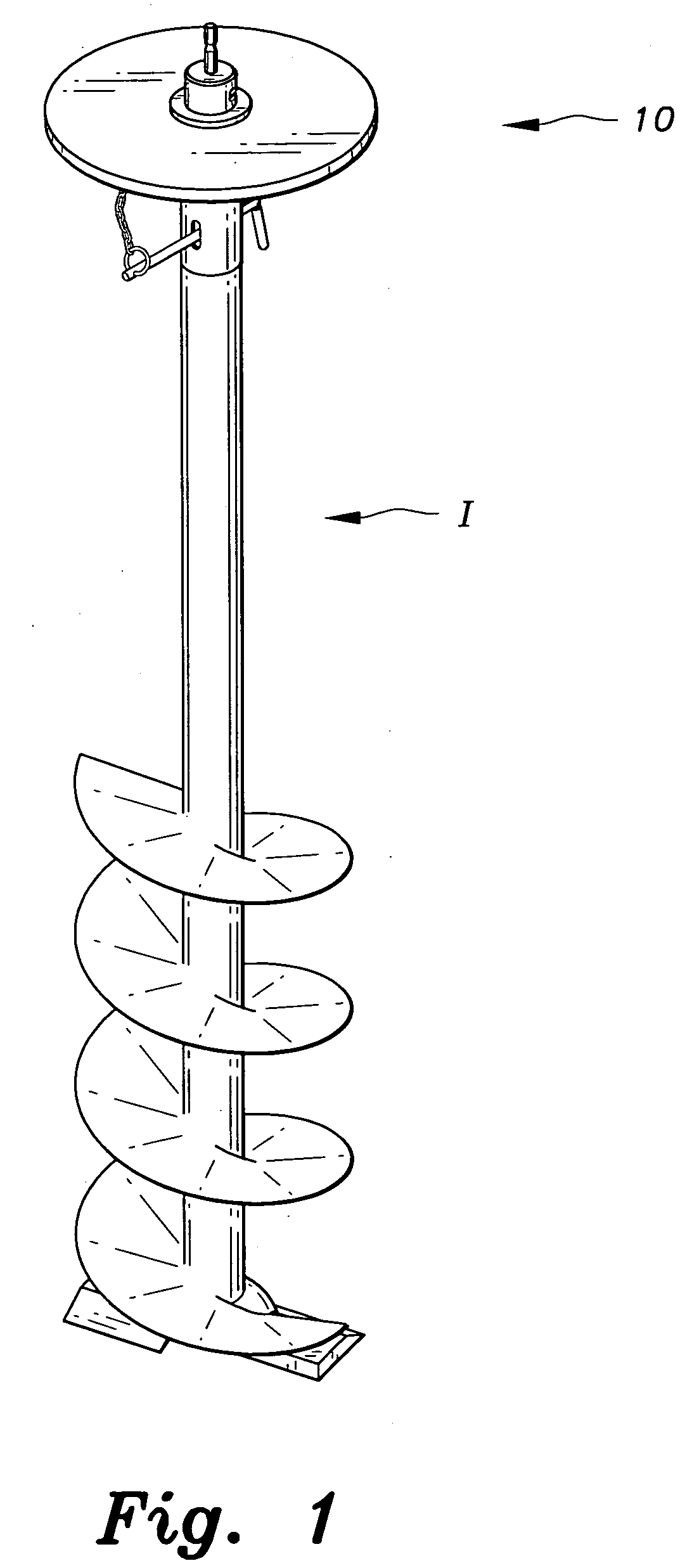
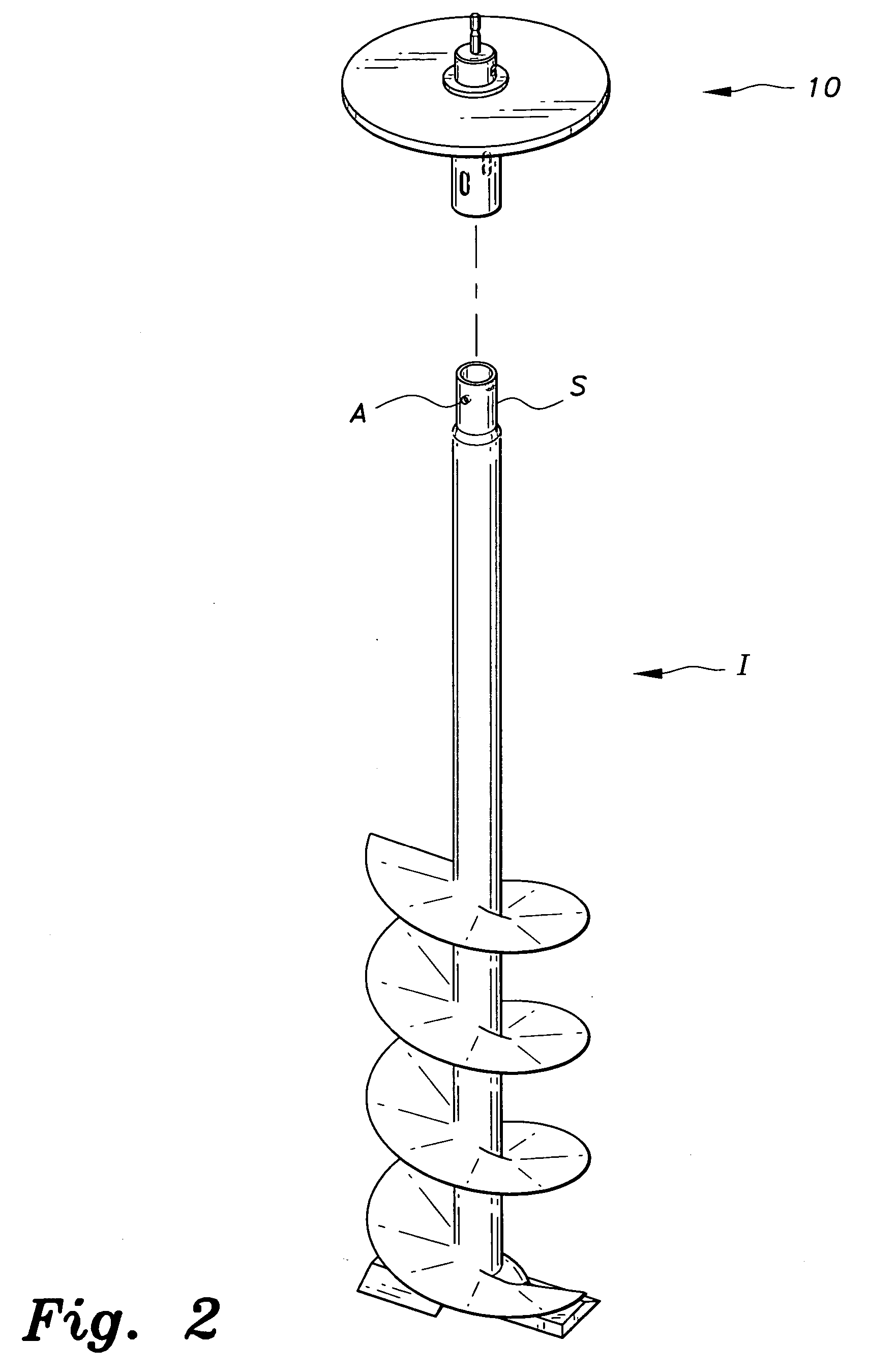
[0025] The present invention is a drill adapter for an ice auger, designated generally as 10 in the drawings. The adapter 10 is designed to allow an ice auger to be powered by a battery-powered drill. As shown in FIGS. 3 and 4, the adapter 10 includes a receiver tube 20, an end cap 50 with a removable drill driver bit 62, a floating shield 30, an internal spring 40, a C-ring clip 70, a locking pin 76 and a setscrew 60.

[0026] The receiver tube 20 is configured for attachment to an ice auger shaft S. Receiver tube 20 is cylindrical in shape with an upper end 24 and a lower end 22. Near the upper end 24 is a circumferential groove 28 for receiving the C-ring clip 70, and near the lower end 22 is a pair of apertures 26 that are positioned on opposite sides of the tube 20. The locking pin 76 is dimensioned to fit through the apertures 26. The locking pin 76 has two elongated segments that are pivotally attached to each other and pivot between a coaxial position and a position in which t...


PUM


Abstract

The drill adapter for an ice auger is an adapter that allows an ice auger to be powered by a battery-powered drill. The device includes a receiver tube that is configured for attachment to an ice auger shaft, and an end cap with a removable driver bit for attachment to a battery-powered drill. The device also includes, as a safety feature, a floating shield that spins freely around the receiver tube thereby allowing rotation of the shield to be stopped while the device is powering an ice auger, and includes a spring within the receiver tube that absorbs vibration.

Description

BACKGROUND OF THE INVENTION [0001] 1. Field of the Invention [0002] The present invention relates to ice augers, and more particularly to an apparatus that enables an ice auger to be powered by a battery-powered drill. [0003] 2. Description of the Related Art [0004] The use of ice augers is well known in the prior art. Typically, a fisherman uses an ice auger during winter to bore a hole through the ice covering a lake for access to fishing below. Early embodiments of ice augers were hand-powered, as exemplified by U.S. Pat. No. 4,819,744, issued Apr. 11, 1989 to T. J. Caswell (funnel hole ice auger). However, boring a hole through a thick layer of ice using a hand-powered ice auger required a great expenditure of strength and energy. As a result, other means for powering ice augers have been developed. For example, U.S. Pat. No. 3,602,321, issued Aug. 31, 1971 to G. Kortschaga; U.S. Pat. No. 3,705,632, issued Dec. 12, 1972 to L. J. Burke; and U.S. Pat. No. 3,731,751, issued May 8, ...

Claims


Application Information

Patent Timeline
Patent Type & Authority Applications(United States)
IPC IPC(8): F25C5/04
CPCF25C5/04E21B7/008
Inventor KOLLASCH, JASON E.THELEN, THOMAS N.BAKER, MONTY R.ENDERSON, GARY M.
Owner KOLLASCH JASON E
Why Eureka
Try Eureka