Supported disc

a technology of supported discs and brake discs, which is applied in the direction of brake discs, brake elements, braking members, etc., can solve the problems of noise and vibration generation risk, and the possibility of disc design, and achieve the effect of keeping the cost of the brake relatively low

Inactive Publication Date: 2005-09-22
HALDEX BRAKE PROD AB
View PDF6 Cites 13 Cited by
  • Summary
  • Abstract
  • Description
  • Claims
  • Application Information

AI Technical Summary

Benefits of technology

[0011] In some embodiments an extra recess may be formed at one side of the brake discs. This assists in keeping the costs of the brake relatively low.

Problems solved by technology

However, if the available space is limited it may not be possible to allow a disc design that is wide enough.
The risk or skewing and / or wobbling is reduced, and thus the risk of noise and vibration generation.

Method used


Image

  • Supported disc
  • Supported disc
  • Supported disc

Examples


first embodiment

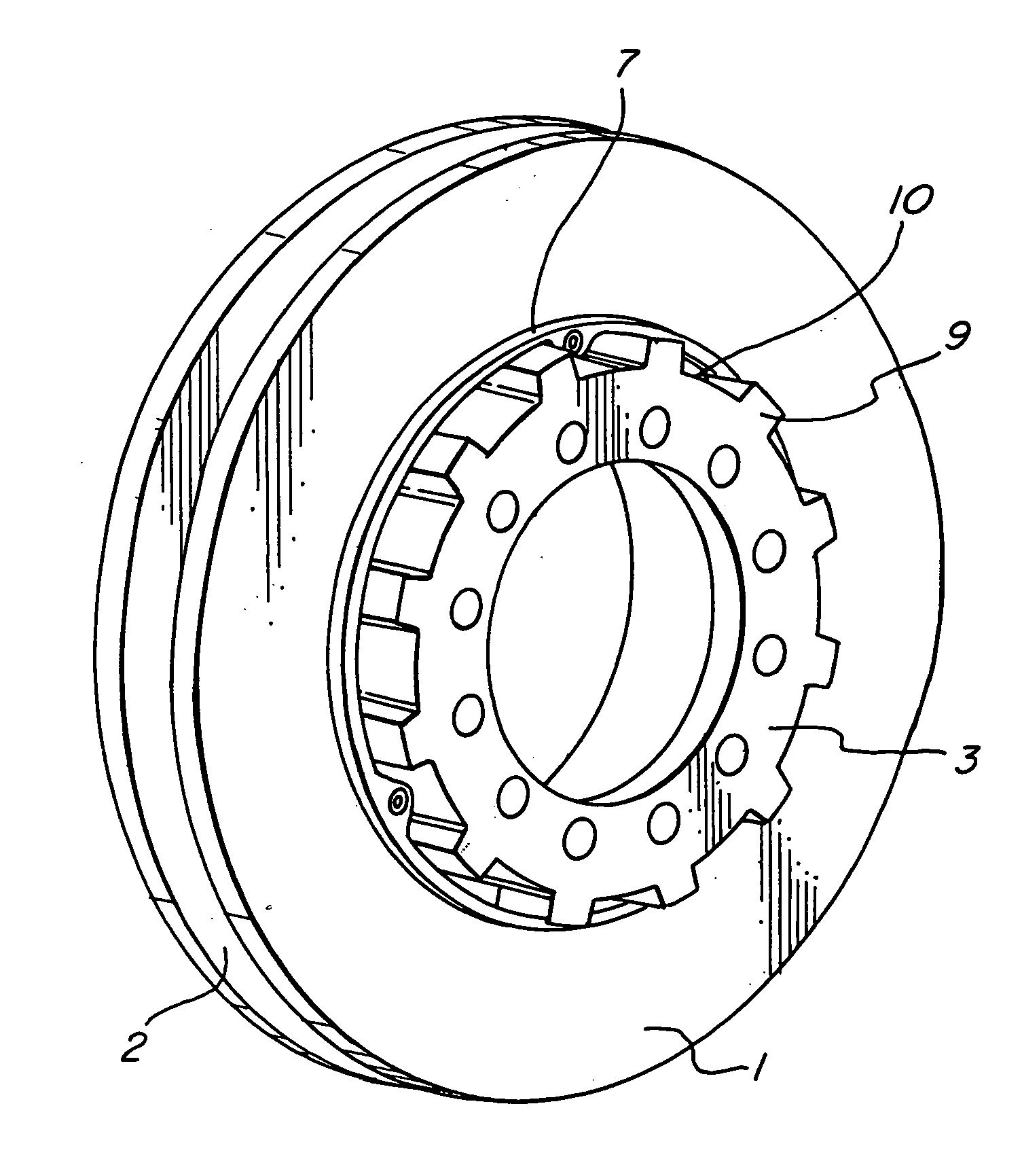
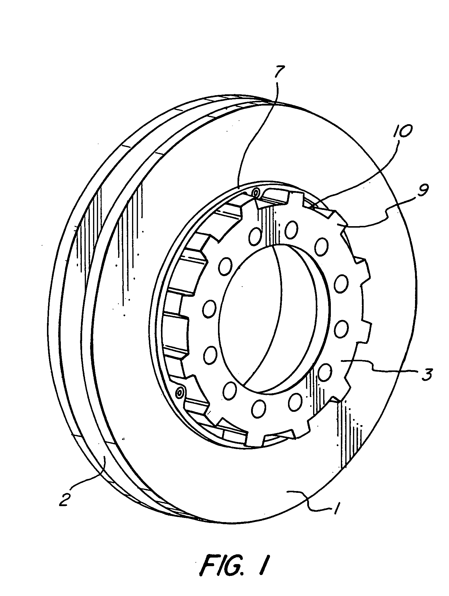
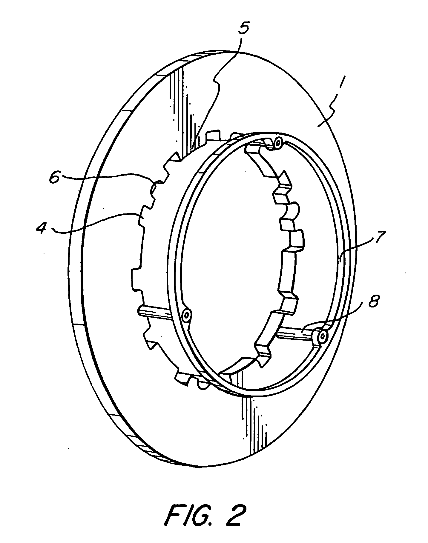
[0024] In a first embodiment the disc brake comprises two sliding brake discs 1, 2 received on a hub 3. The brake discs 1, 2 are received sliding in relation to the hub 3 by means of splines 4, 5; 9, 10 on the brake discs 1, 2 and the hub 3, respectively. The splines on the brake discs 1, 2 are formed of grooves 4 and raised parts 5. In the same way the splines of the hub 3 are formed of raised parts 9 and grooves 10. The splines 4, 5; 9, 10 have a general axial extent in the discs 1, 2 and the hub 3, respectively.

[0025] On at least one side of each brake disc 1, 2 a ring 7, 11 is arranged on an axial distance from the brake disc 1, 2. The rings 7, 11 are attached to the brake disc 1, 2 by means of pins 8, 12. One end of each pin 8, 12 is fixed to the brake disc 1, 2 and the other end of the pin 8, 12 is fixed to the ring 7, 11. The inner diameter of each ring 7, 11 corresponds with the outer diameter of the hub 3, i.e. the diameter formed of the raised parts 9 of the splines of the...

third embodiment

[0042] The form of the rings 47, 51 and legs 48, 52 of this third embodiment makes it suitable to simply fix the rings 47, 51 to the brake discs 41, 42 by snapping the rings 47, 51 to the discs 41, 42.

[0043] Furthermore, the form of the legs 48, 52 and the recesses 46 are adapted to each other to keep the legs 48 firm in the recesses 46. To further fixate each ring 47, 51 to the hub 43 the legs 48 may be fixed to the brake disc 41, 42 in any suitable way. Such fixation may be screws, rivets, welding, soldering, glue or other fastening means.

[0044] The legs 48 of the rings 47, 51 will slide in the grooves 50 of the splines of the hub 43. The inner diameter of each ring 47, 51 is adapted to the outer diameter of the hub 43.

[0045] As for the previous embodiment the distance between each ring 47, 51 and the brake disc 41, 42 should be enough to give room for new brake pads (not shown).

[0046] In a fourth embodiment (FIGS. 8 and 9) brake discs 61, 62 are received on a hub 63. As for th...


PUM


Abstract

The present invention concerns a disc brake having one or more sliding or floating brake discs. The discs are received on a hub by means of splines on the discs and hub, respectively. The discs have means to widen the support of each disc on the hub. Said means may have the form of one or more rings, pins and/or clips attached to the discs.

Description

[0001] This application is a continuation of pending International Patent Application No. PCT / EP2003 / 009934 filed Sep. 8, 2003, which designates the United States and claims priority of pending Swedish Application No. 0202705-0 filed Sep. 10, 2002.FIELD OF THE INVENTION [0002] The present invention concerns a disc brake having one or more sliding or floating brake discs. More specifically it concerns means for support of said sliding disc(s). [0003] The present invention is developed for disc brakes having a fixed caliper and one or more sliding discs. However, a person skilled in the art realizes that the invention may also be used with other types of brakes, e.g. disc brakes having one fixed disc, one or more sliding discs and a sliding (floating) or fixed caliper. PRIOR ART [0004] Besides low costs of manufacture and maintenance, a general object when designing brakes is that they should be as compact as possible and have low weight. Thereby they are relatively easy to adapt to d...

Claims


Application Information

Patent Timeline
Patent Type & Authority Applications(United States)
IPC IPC(8): F16D55/00F16D55/36F16D65/12
CPCF16D55/36F16D65/12F16D2055/0062F16D2065/1396F16D2065/1384F16D2065/1392F16D2065/1368
Inventor GRIPEMARK, JOAKIMSEVERINSSON, LARSORTEGREN, ANDERSKALL, PATRIK
Owner HALDEX BRAKE PROD AB
Why Eureka
Try Eureka