Use of a photovoltaic element as sensor for checking the functioning of transmitters in the infrared range

a technology of infrared range and photovoltaic element, which is applied in the direction of photometry using electric radiation detectors, optical radiation measurement, instruments, etc., can solve the problems of inability to verify the function of infrared radiation for testing purposes, and inability to quantitatively measure the radiation power or output of the headlight, etc., to achieve reliable information regarding the functionality and the ability to verify the functionality of the emi

Active Publication Date: 2005-09-22
BAYERISCHE MOTOREN WERKE AG
View PDF8 Cites 1 Cited by
  • Summary
  • Abstract
  • Description
  • Claims
  • Application Information

AI Technical Summary

Benefits of technology

[0018] According to a further example of use, according to claim 4, a filter is provided in front of the photovoltaic element, which makes it possible to shield visible light partially or completely from the impinging upon the photovoltaic element, in comparison to which the infrared radiation passes through the filter unimpeded or substantially unimpeded or, as the case may be, substantial parts of the infrared radiation are unimpeded or substantially unimpeded from passing through the filter and can impinge upon the photovoltaic element. Thereby a very reliable check of functionality of emitters in the infrared range is ensured.
[0019] It has been found particularly advantageous to employ an inventive photovoltaic element in the functionality check of infrared headlights for vehicles, which routinely or regularly require an inspection at a motor vehicle service station so that even a slight possibility of interference of other traffic participants by a malfunctioning of the infrared headlight is precluded or minimized. Therein the employment of this photovoltaic element for checking the functionality of an infrared vehicle headlight has been found particularly useful, since these can be constructed very simply and very robustly and thus can provide very reliable information regarding the functionality of the vehicle headlight.

Problems solved by technology

Further, it is not possible to undertake a quantitative measurement of the radiation power or output of the headlight.
Likewise, no quantitative measurement is possible in infrared vision devices (image transformers).
With the naked eye the infrared radiation cannot be verified for checked for test purposes.

Method used


Image

  • Use of a photovoltaic element as sensor for checking the functioning of transmitters in the infrared range
  • Use of a photovoltaic element as sensor for checking the functioning of transmitters in the infrared range

Examples


Embodiment Construction

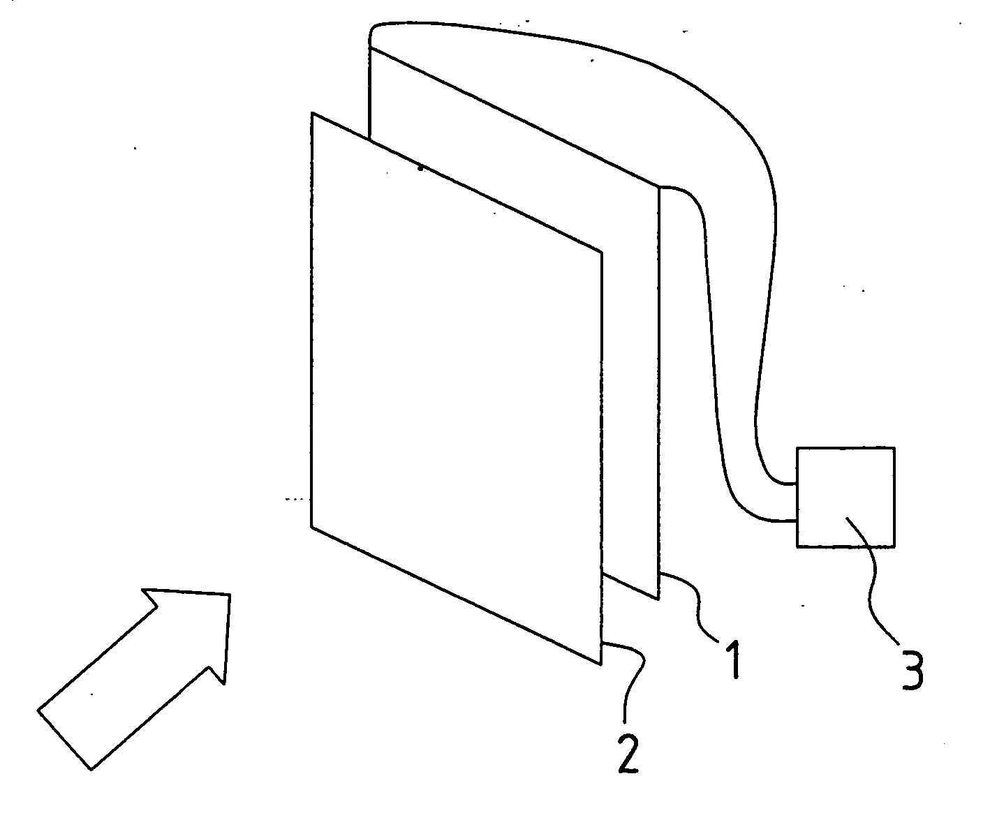
[0024]FIG. 1 shows a first sensor array for integral measurement of the beam power. Therein a photovoltaic element 1 can be seen, which could be, for example, a normal silicon solar cell. Further, a plastic VIS-filter 2 is provided in front of the photovoltaic element 1, which is transmissive only for light in the infrared range.

[0025] A galvanometer 3 is connected to the photovoltaic element 1.

[0026] With the shown sensor element the beam power of an infrared headlight can be measured. In order to provide quantitative information, it is further necessary to know the distance to the infrared headlight, in order to ensure that the beam power of the headlight is fully acquired by the photovoltaic element.

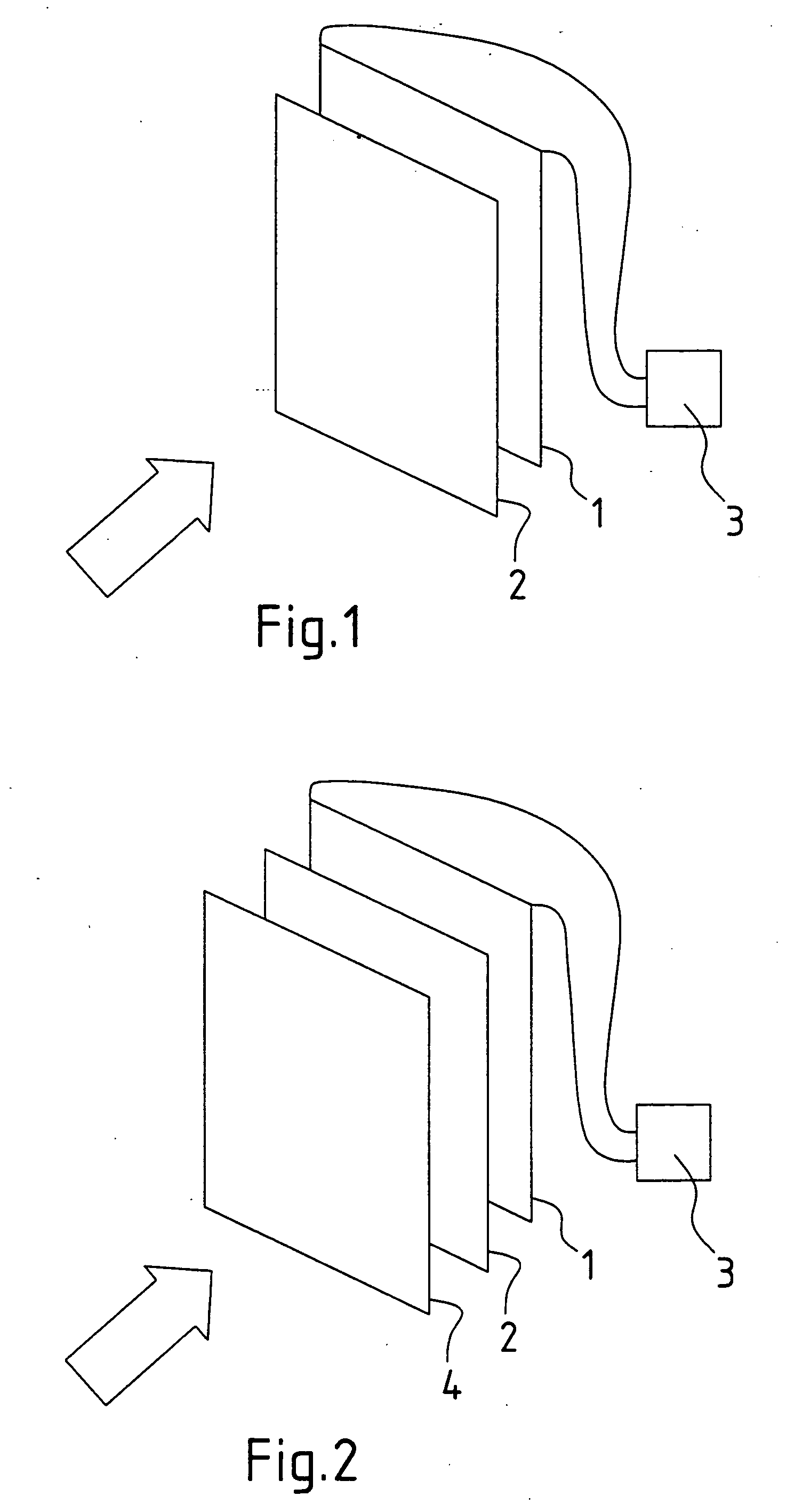
[0027]FIG. 2 shows a further sensor array. Therein a shield 4 is provided in addition to the elements shown in FIG. 1. By this shield the emission power is allowed to pass through in only a certain spatial angle. By the appropriate positioning of the shield the corresponding data f...


PUM


Abstract

The present invention concerns the use of a photovoltaic element as sensor for checking the functionality of transmitters in the infrared range.

Description

BACKGROUND OF THE INVENTION [0001] 1. Field of the Invention [0002] The invention concerns the use of a photovoltaic element as sensor for testing the functioning of transmitters in the infrared range. [0003] 2. Related Art of the Invention [0004] Conventional radiation measurement devices can be employed for carrying out tests of the functioning of, in particular, headlights of motor vehicles in the infrared range. This type of photometer always has only a limited surface upon which a precise measurement is possible. Further, a measurement is possible mainly in the region of lower power. The headlights in infrared range play a role in applications in motor vehicles in systems for improving visibility in darkness. [0005] A further function check of headlights is provided by the evaluation of a camera image. If no camera image is presented, then in this case it must first be determined whether it is the headlight or the camera that is defective. Further, it is not possible to underta...

Claims


Application Information

Patent Timeline
Patent Type & Authority Applications(United States)
IPC IPC(8): G01J1/42G01J5/28
CPCG01J1/4257G01J2001/4247G01J5/28
Inventor MOISEL, JOERG
Owner BAYERISCHE MOTOREN WERKE AG
Why Eureka
Try Eureka