Motor armature having distributed windings for reducing arcing

Inactive Publication Date: 2005-09-22
BLACK & DECKER INC
View PDF22 Cites 14 Cited by
  • Summary
  • Abstract
  • Description
  • Claims
  • Application Information

AI Technical Summary

Benefits of technology

[0012] The above winding pattern continues in alternating fashion such that an overlapping of the coils occurs around the lamination stack. In effect, all of the first subcoil portions shift their magnetic axes forward with respect to rotation of the armature, and all of the second coil portions shift their magnetic axes backward relative to the direction of armature rotation. With a desired turns ratio between the two subcoil portions of each coil, which ratio may vary considerably but is preferably about 3:1, the above described winding pattern smoothes out the “unevenness” in the magnetic coupling between adjacent armature coils, thus improving commutation efficiency. This also improves the commutation efficiency for the second subcoil portion of each coil, thus reducing brush arcing. This in turn serves to significantly reduce EMI. The reduction of EMI eliminates the need for expensive EMI suppression components that have previously been required for use with the motor brushes to ensure that EMI levels remain below regulated limits.
[0013] In an alternative preferred embodiment of the present invention a motor is disclosed having an armature that incorporates a plurality of coils wound in an overlapping fashion. Alternating ones of the coils are segmented into serially coupled subcoils that overlap with non-segmented coils. This pattern permits the same number of winding turns to be used for the two subcoil portions, while still obta

Problems solved by technology

This can also cause electro-magnetic interference (EMI) to be generated which exceeds acceptable levels

Method used


Image

  • Motor armature having distributed windings for reducing arcing
  • Motor armature having distributed windings for reducing arcing
  • Motor armature having distributed windings for reducing arcing

Examples


Embodiment Construction

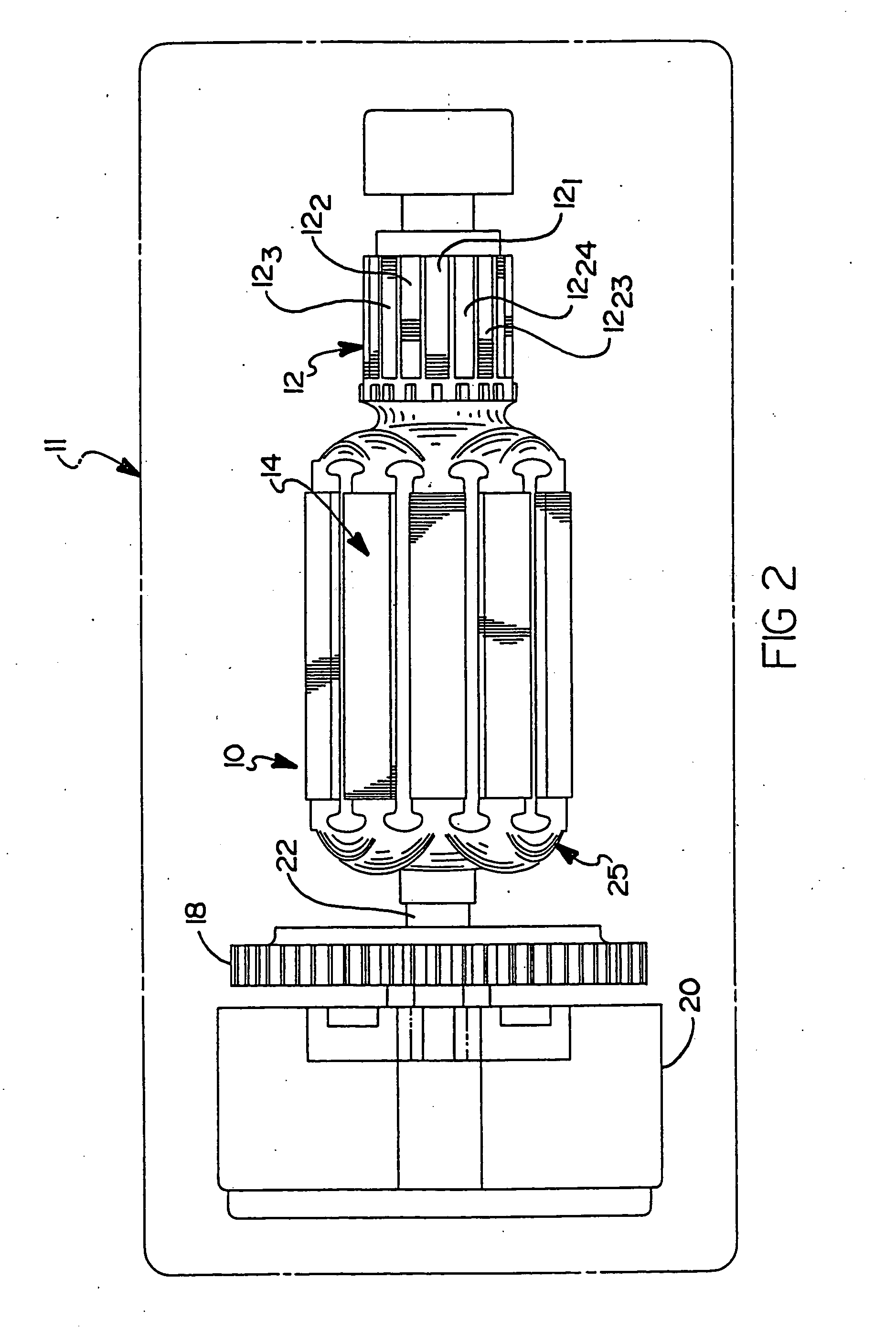
[0026] Referring to FIG. 2, there is shown an armature 10 for a brush commutated electric motor 11 having a plurality of coils wound in accordance with the teachings of the present invention. The armature 10 includes a commutator 12 which, merely by way of example, includes 24 independent commutator segments 121-1224. A lamination stack 14 is used to support a plurality of 24 coils 251-2524 wound thereon. An armature shaft 22 extends through the lamination stack 14 and is fixedly coupled to a gear reduction assembly 20 and also to a fan 18. It will be appreciated, though, that the fan 18 and the gear reduction assembly 20 are optional and not essential to the armature 10 of the present invention, and shown merely because they are components that are often used in connection with an armature for an electric motor.

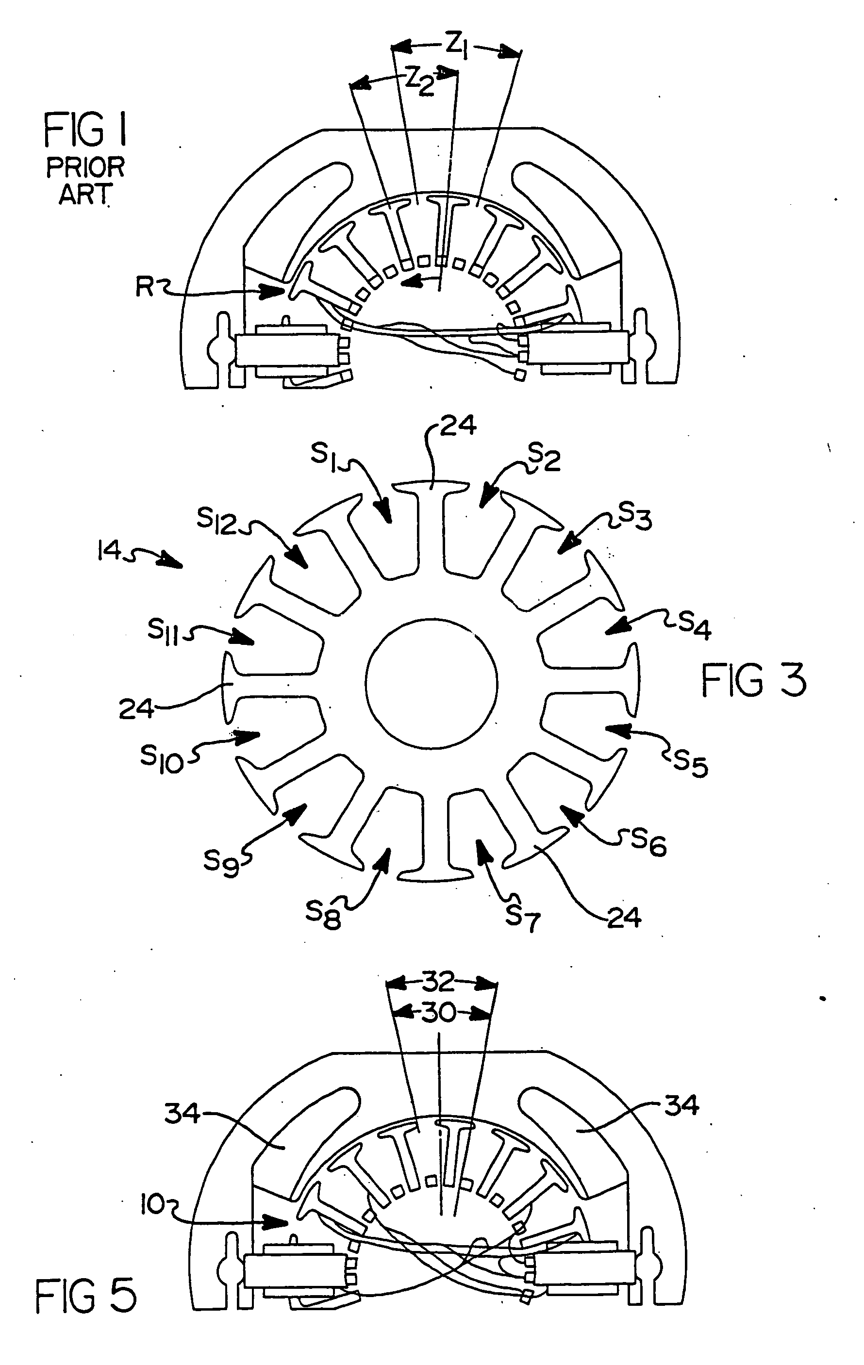
[0027] Referring to FIG. 3, the lamination stack 14 is illustrated without any coils wound thereon. The lamination stack 14 includes a plurality of radially projecting lami...


PUM

PropertyMeasurementUnit
Magnetismaaaaaaaaaa

Abstract

An armature for a brush commutated electric motor having a distributed coil winding arrangement for reducing brush arcing and electromagnetic interference (EMI). The winding pattern involves winding a first coil into a first pair of slots of the armature. A second coil having a first subcoil portion is then wound into the same slots as the first coil, while a second subcoil portion of the second coil is wound into a pair of slots that is offset by one slot position from the first pair of slots. The two subcoil portions have the same number of turns, and the total turns of the two subcoil portions equals the number of turns of the first coil. A third coil is then wound in the same slots as the second subcoil portion of the second coil. The third coil has the same number of turns as the first coil. This pattern is repeated around the armature. In a two coil per slot armature, this pattern enables the magnetic axis of each coil to be maintained at a constant angular position relative to the commutator bars to which it is coupled without the need for using uneven numbers of turns for the two subcoil portions of each segmented coil.

Description

CROSS-REFERENCE TO RELATED APPLICATIONS [0001] This application is a continuation-in-part of U.S. Ser. No. 10 / 404,857, filed Apr. 1, 2003, presently pending, which is a divisional of U.S. Ser. No. 09 / 594,357, filed Jun. 14, 2000, and presently issued as U.S. Pat. No. 6,566,782 on May 20, 2003.FIELD OF THE INVENTION [0002] 1. Technical Field [0003] This invention relates to electric motors, and more particularly to a winding pattern for winding the coils on an armature in a manner to reduce electromagnetic interference and arcing at the brushes in contact with the commutator of the armature. [0004] 2. Background of the Invention [0005] Present day brush commutated electric motors include an armature having a plurality of coils wound in slots formed in the lamination stack of the armature. With traditional motor designs, the lamination stack of the armature forms a plurality of circumferentially arranged slots extending between adjacent pairs of lamination posts. Typically, two coils ...

Claims


Application Information

Patent Timeline
IPC IPC(8): H02K23/30
CPCH02K23/30Y10T29/49009Y10T29/49011H02K3/38
Inventor WALTER, RICHARD T.WANG, REN HONG
Owner BLACK & DECKER INC
Why Eureka
Try Eureka