Image formation assisting device, image formation assisting method, and image formation assisting system

a technology of image data and ctp method, applied in the direction of visual presentation using printers, digital output to print units, instruments, etc., can solve the problem that the image data of the ctp method cannot be used in conjunction with the image data for on-demand printing

Inactive Publication Date: 2005-09-22
FUJIFILM BUSINESS INNOVATION CORP
View PDF1 Cites 17 Cited by
  • Summary
  • Abstract
  • Description
  • Claims
  • Application Information

AI Technical Summary

Problems solved by technology

Hence, at the present time, the image data for the CTP method can not be used in conjunction with the image data for the on-demand printing.

Method used


Image

  • Image formation assisting device, image formation assisting method, and image formation assisting system
  • Image formation assisting device, image formation assisting method, and image formation assisting system
  • Image formation assisting device, image formation assisting method, and image formation assisting system

Examples


embodiment 1

[0039] One example of the an embodiment of the present invention will be described in detail with reference to the drawings.

[Image Forming System]

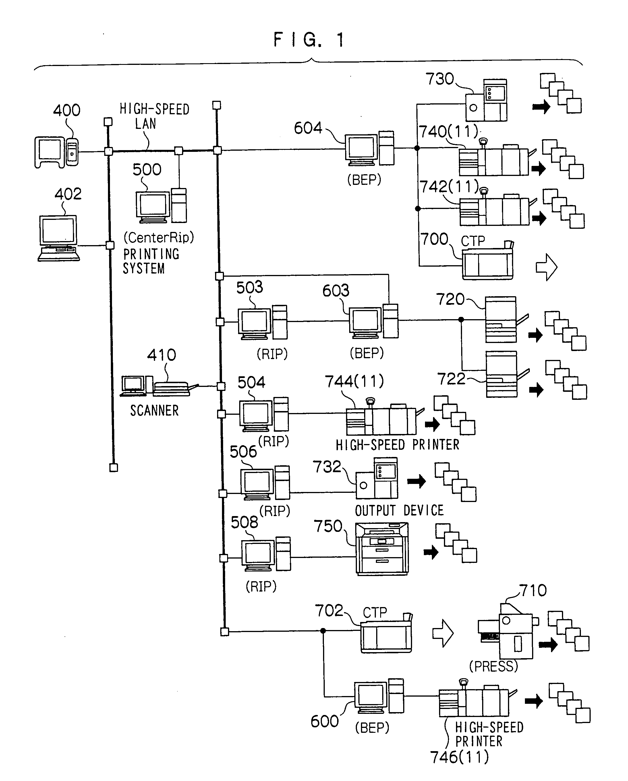
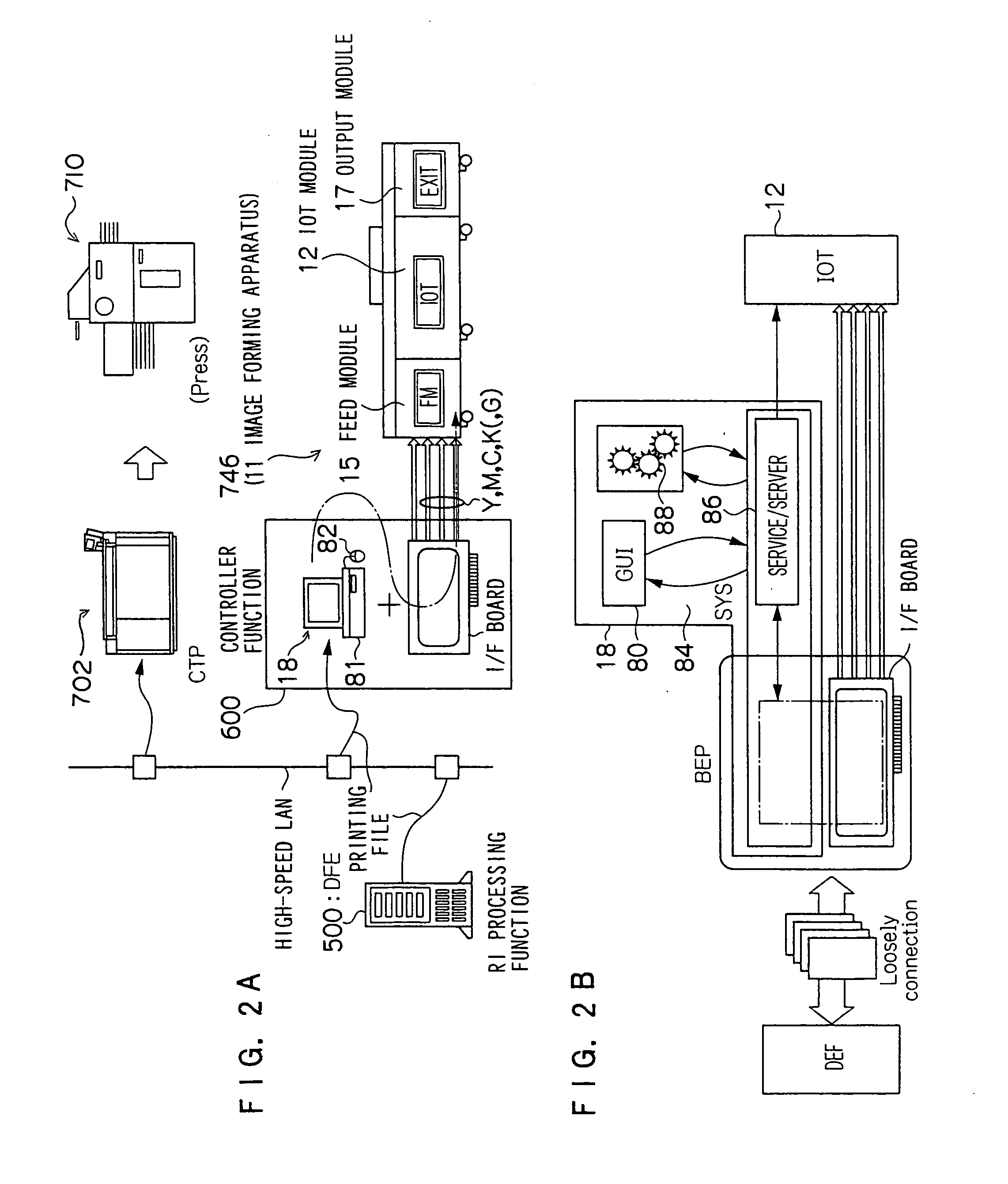
[0040]FIG. 1 is an illustration to show the general configuration of an image forming system in accordance as a result embodiment. The image forming system has a high-speed LAN (Local Area Network) using a general-purpose communications protocol and client terminals 400 and 402 for inputting electronic data (printing data) described in, for example, a page description language (PDL) are connected to the high-speed LAN. The client terminals 400 and 402 are computers capable of executing various kinds of application programs under different operating systems (OS). A scanner 410, which reads an image on an original document and outputs the data of the image, is also connected to the high-speed LAN. Further, DFE processors 500, 503, 504, 506, and 508, BEPs (back end processor) 600, 603, and 604 as an image formation assisting device of the i...

embodiment 2

[0102] Another example of the embodiment of the invention will be described in detail with reference to the drawings.

[0103] Since the image forming system and the configuration example are the same as those in the embodiment 1, their descriptions will be omitted, and the same elements are denoted by the same reference symbols.

[0104] The embodiment 1 does not present any problem in the case of printing an image only on the top of the paper, but when an image is also printed on the bottom of the paper, the image to be printed on the bottom of the paper is outputted from another plate. Hence, in this embodiment, further, the BEP 600 ascertains the allocated layout of each plate, position information, instruction of the printing side (top (front) and / or bottom (back)) of the paper to be provided to the engine side, and the page sequence of the engine side, and sorts the respective electronically edited images from the image data of a large size also in consideration of the printing si...

embodiment 3

[0125] Hereafter, still another example of an embodiment of the invention will be described in detail with reference to the drawings.

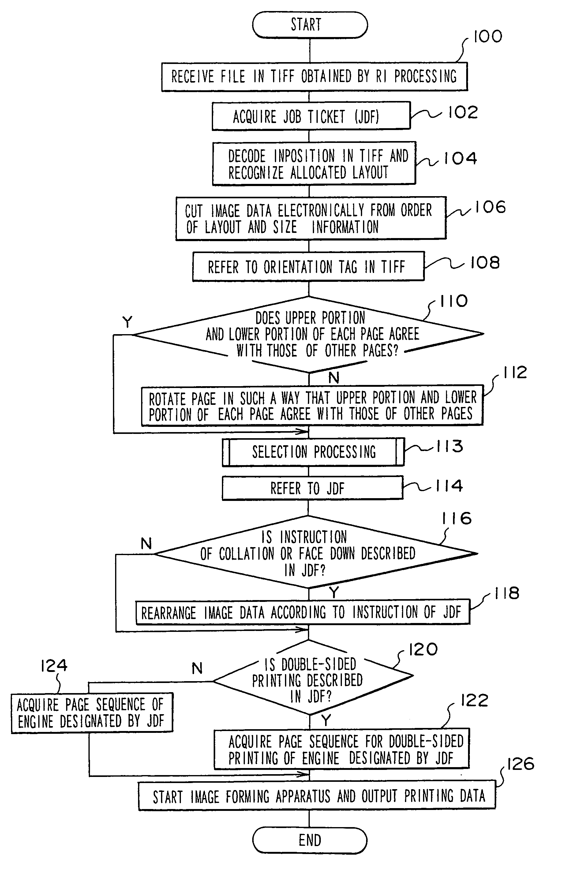
[0126] When compared with the embodiment 2, this embodiment is different in that whether the image is printed by the CTP device 702 or by the POD (image forming apparatus 11) can be selected according to the kind of image and the like of each electronically edited page. The other elements are the same as those in the embodiment 2, and hence descriptions thereof will be omitted. Further, the same elements are denoted by the same reference symbols. FIG. 10 is a flow chart showing one example of the processing performed at this time by the BEP. When compared with the flow chart shown in FIG. 7 in the embodiment 2, this flow chart is different in that a selection processing step 113 is added.

[0127] When the image data of a large size for the CTP method is produced by the RIP section 510 and is outputted to the BEP 600, in the BEP 600, first, at step 100,...


PUM


Abstract

An image formation assisting device calculates layout information such as allocation and pasting position of each page by a BEP from a file size with reference to the orientation tag of image file data in a TIFF produced by an RIP and cuts image data electronically according to the result of the calculation and makes the upper portion and lower portion of each page correspond with those of the other papers and rearranges each electronically cut page according to an instruction of collation or face-down, when the instruction is provided, and activates a print engine to start and specifies predetermined paper automatically and outputs the image data to the print engine. As a result, there is provided an image formation assisting device capable of using image data for CTP for on-demand printing.

Description

CROSS-REFERENCE TO RELATED APPLICATION [0001] This application claims priority under 35 USC 119 from Japanese Patent Application Nos. 2004-74617, 2004-74618, and 2004-74619, the disclosures of which are incorporated by reference herein. BACKGROUND OF THE INVENTION [0002] 1. Field of the Invention [0003] The present invention relates to an image formation assisting device, an image formation assisting method, and an image formation assisting system, and, for example, to an image formation assisting device, an image formation assisting method, and an image formation assisting system for outputting data to an image forming apparatus having a so-called printing function of forming an image on a recording medium, such as a color copier, a facsimile, a printer, or the like. [0004] 2. Description of the Related Art [0005] In conventional printing (for example, offset printing), intermediate products, for example, paper prints (photographic paper) such as photo compositions, layout paper, n...

Claims


Application Information

Patent Timeline
Patent Type & Authority Applications(United States)
IPC IPC(8): G06F15/00G06K15/02H04N1/387
CPCG06K15/02H04N1/387H04N1/32459H04N1/32358
Inventor UEJO, HIROYOSHIKITAGAWA, TOSHIKAZU
Owner FUJIFILM BUSINESS INNOVATION CORP
Why Eureka
Try Eureka