
Series arc detection

a series arc and detection technology, applied in the field of circuit interruption, can solve the problems of damage or fire, prior art circuit interrupters do not differentiate the frequency content change between switching loads, and low-level arcs in series with loads that are beyond the capabilities of those techniques,

Active Publication Date: 2005-09-22
ABB (SCHWEIZ) AG
View PDF19 Cites 29 Cited by
  • Summary
  • Abstract
  • Description
  • Claims
  • Application Information

AI Technical Summary

Benefits of technology

The patent describes a system and method for detecting series arcs in a circuit interrupter. The system includes a frequency analyzer that receives an input signal and compares it to a reference signal band to determine if it is a series arc signal or a load. If the tested signal is determined to be a series arc signal, a trip signal is sent to separate the circuit interrupter's contacts. The technical effect of this patent is to provide a reliable and accurate way to detect and prevent damage caused by series arcs in circuit interrupters, which can help to improve safety and reliability in power distribution systems.

Problems solved by technology

However, lower level arcs in series with a load may be beyond the capabilities of those techniques.
Prior art circuit interrupters do not differentiate the frequency content change between switching loads such as drills, hair dryers, and air compressors and those with series arcs.
Even so, such arcs may cause damage or start a fire if they occur near combustible material.
There are problems associated with merely increasing the sensitivity of prior techniques.

Method used


Image

  • Series arc detection
  • Series arc detection
  • Series arc detection

Examples


Embodiment Construction

[0021] The system disclosed herein detects series arcing by analyzing the frequency content of the sensed current in a power line.

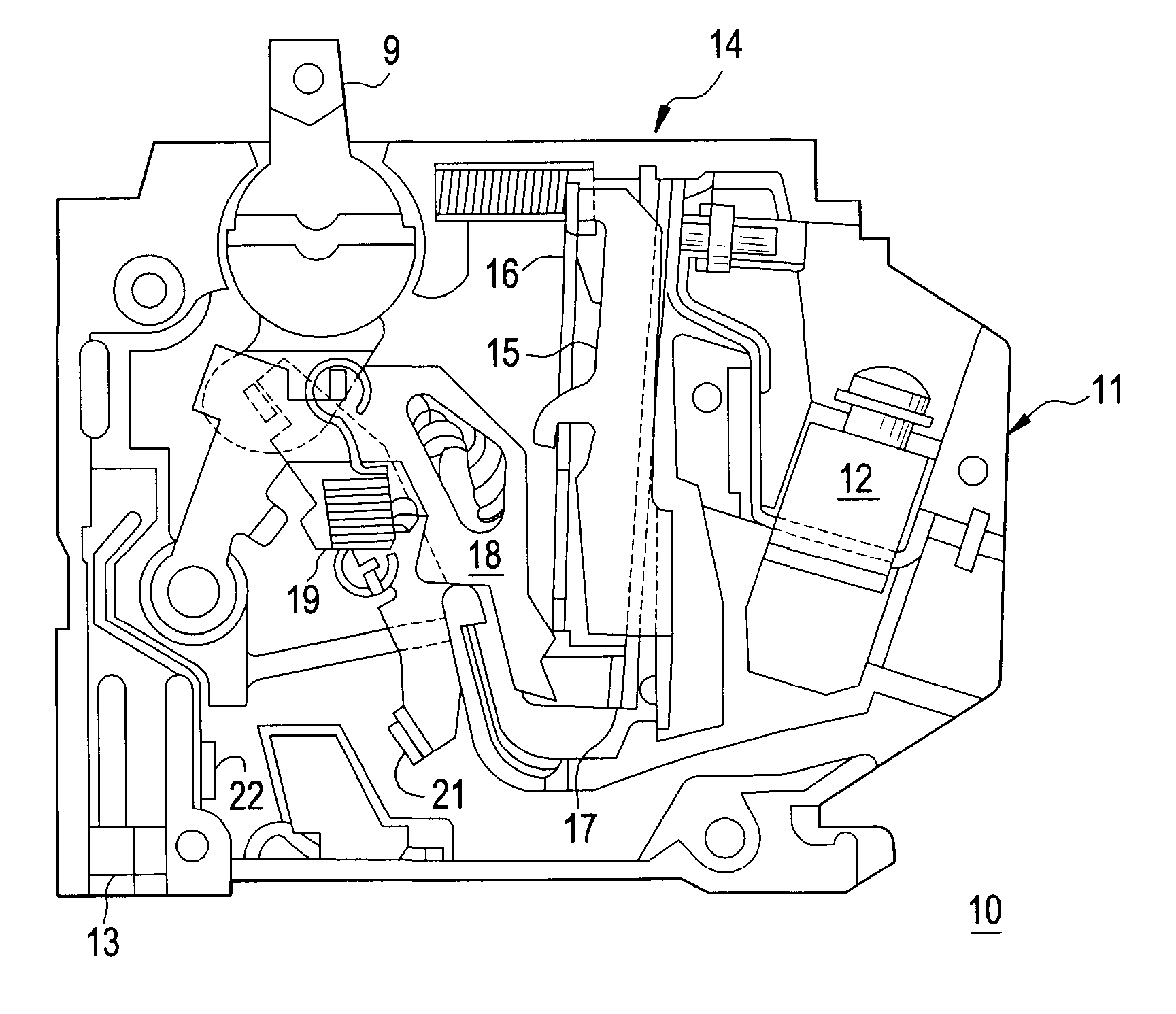
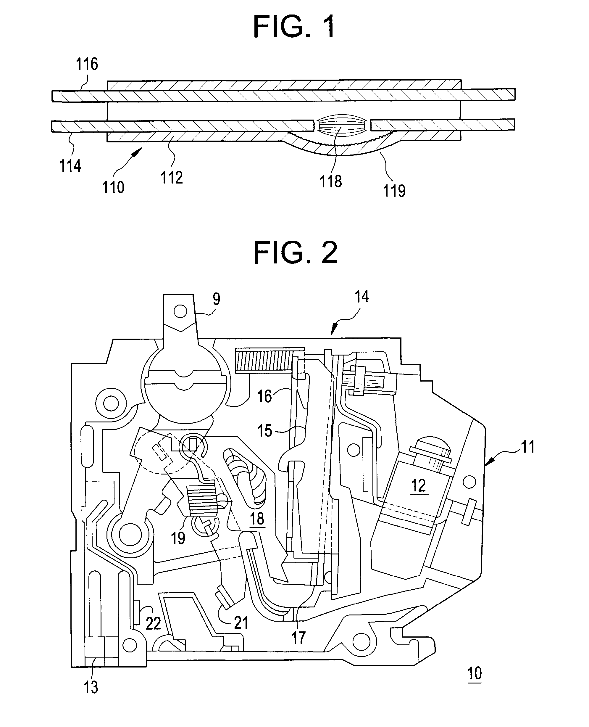
[0022] A circuit breaker 10 having an externally operated handle 9 is shown in FIG. 2 and may include a molded plastic case 11. The circuit current transfers from the load terminal lug 12, thermal magnetic trip unit 14, fixed and moveable contacts 22, 21 to the line terminal stab 13. The thermal-magnetic trip unit includes a magnet 15 and armature 16 that are arranged for operation upon occurrence of so called “short circuit” and short time” fault conditions within the protected circuit. “Long time” overcurrent protection may be provided by means of a bimetal 17. The operating cradle 18 may interact with armature 15 to hold the contacts from being separated by the bias provided by the operating spring 19.

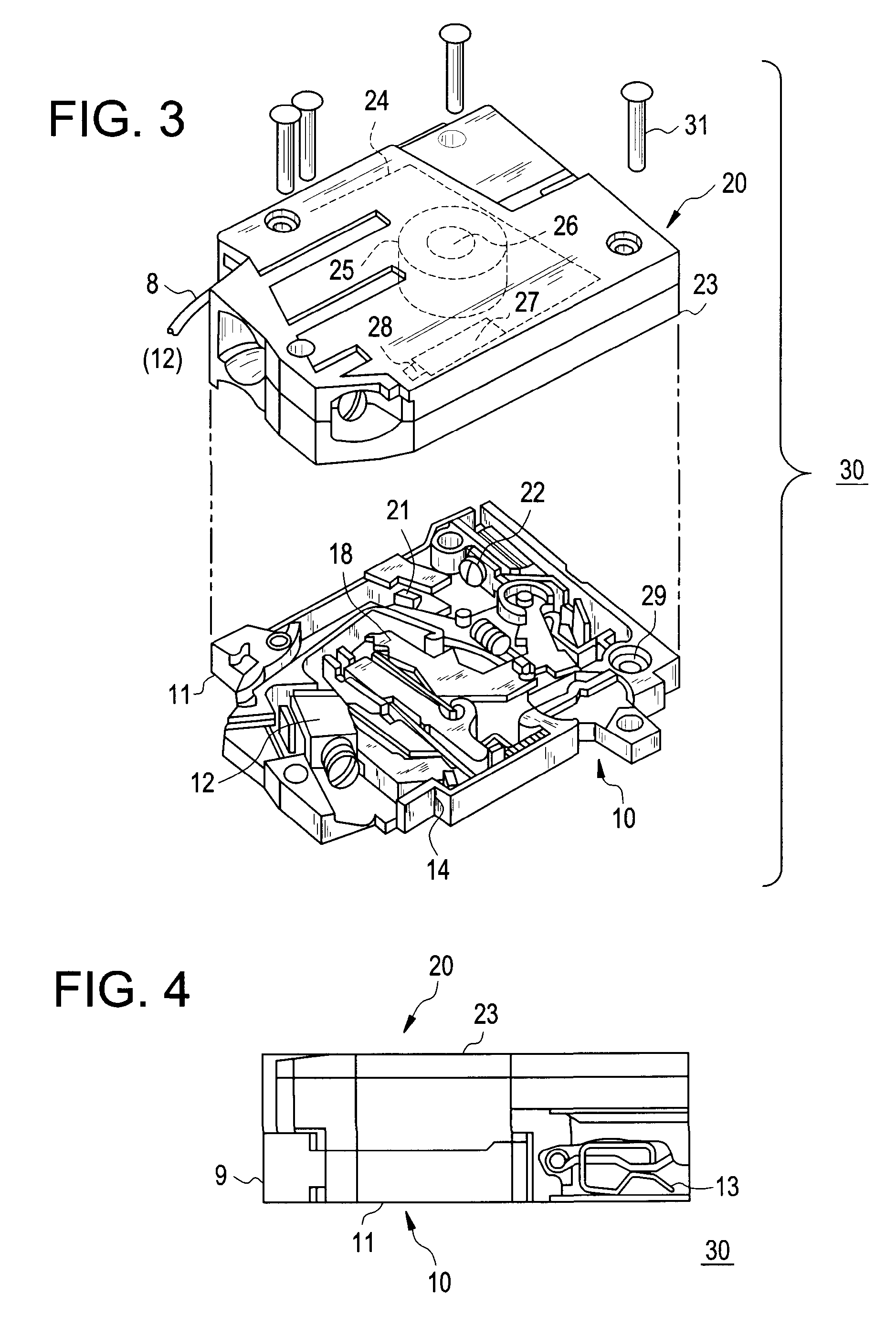
[0023] An exemplary combined arcing fault and circuit breaker unit 30 is shown in FIGS. 3 and 4 and may be formed by attaching a case 23 of an arcing f...


PUM


Abstract

A frequency harmonic identifier for detecting series arcs on a power line includes a frequency analyzer for providing the harmonic content of a sensed current signal and a decision logic for comparing a tested signal to at least one reference signal band. The reference signal band or bands may represent a variety of common loads and if the tested signal does not match any of the sets of reference signal bands, then the logic determines the tested signal to be a series arc signal. The frequency harmonic identifier may be provided within a circuit interrupter and may issue a trip signal if the tested signal is determined to be a series arc signal. A method for detecting series arcs includes sensing current on a power line and providing a sensed current signal as an input signal to a frequency harmonic identifier, performing a Fast Fourier Transform on the input signal for providing a tested signal, accessing a storage area storing at least one reference signal band, comparing the tested signal to the at least one reference signal band and determining if the tested signal is a series arc signal through comparison and, if the test signal is a series arc signal, sending a trip signal. A storage medium may also be encoded with machine-readable computer program code for detecting series arcs on a power line, wherein the storage medium includes instructions for causing a computer to implement the method.

Description

BACKGROUND OF INVENTION [0001] This invention is generally related to circuit interruption, and, more particularly, this invention is related to detecting series arcing in an arc fault circuit interrupter. [0002] Arcing is the luminous discharge of electricity across an insulating medium, usually accompanied by the partial volatilization of the electrodes. Arcing faults in ac electrical systems are of two types: parallel arcs and series arcs. In a parallel arcing fault, the arc occurs across two conductors in the branch circuit or extension cords plugged into it, at a site where the insulating media separating the two conductors has been compromised. The arc may occur across the line and neutral conductors or the line and ground conductors, or in the case of reverse polarity where the line voltage is reverse polarized, between the neutral and ground conductors. The current through the parallel arc fault is not limited by the impedance of the load, but rather by the available current...

Claims


Application Information

Patent Timeline
Patent Type & Authority Applications(United States)
IPC IPC(8): H02H1/00H02H7/00
CPCH02H1/0015
Inventor RIVERS, CECIL JR.ADELEYE, ADEKUNLETARDIF, MARCEL
Owner ABB (SCHWEIZ) AG
Learn More