
Method for securing a glenoid component to a scapula

a technology of glenoid components and scapulas, which is applied in the field of glenoid components, can solve the problems that glenoid components designed to be secured to the scapula by the use of bone cement generally cannot be secured to the scapula without the use of the sam

Inactive Publication Date: 2005-09-22
DEPUY PROD INC
View PDF19 Cites 59 Cited by
  • Summary
  • Abstract
  • Description
  • Claims
  • Application Information

AI Technical Summary

Benefits of technology

"The present invention provides a new and improved glenoid component for securement to a glenoid surface of a scapula for providing a bearing surface for a head portion of a humerus. The glenoid component includes a body portion with a first surface for contacting the glenoid surface and a second surface for receiving the head portion of the humerus. It also includes an anchor peg and a first stabilizing peg for securely attaching the glenoid component to the glenoid surface. The glenoid component is designed to prevent movement of the body portion relative to the glenoid surface and to provide a stable and secure bearing surface for the humerus. The invention also provides a new and improved method for securing the glenoid component to the glenoid surface."

Problems solved by technology

However, use of such two-piece glenoid components has a number of drawbacks associated therewith.
In addition, over time wear of the plastic insert inherently occurs at the interface between plastic insert and the metal backing.
Glenoid components which have been designed to be secured to the scapula by the use of bone cement generally cannot be secured to the scapula without use of the same.

Method used


Image

  • Method for securing a glenoid component to a scapula
  • Method for securing a glenoid component to a scapula
  • Method for securing a glenoid component to a scapula

Examples


Embodiment Construction

[0026] While the invention is susceptible to various modifications and alternative forms, a specific embodiment thereof has been shown by way of example in the drawings and will herein be described in detail. It should be understood, however, that there is no intent to limit the invention to the particular form disclosed, but on the contrary, the intention is to cover all modifications, equivalents, and alternatives falling within the spirit and scope of the invention as defined by the appended claims.

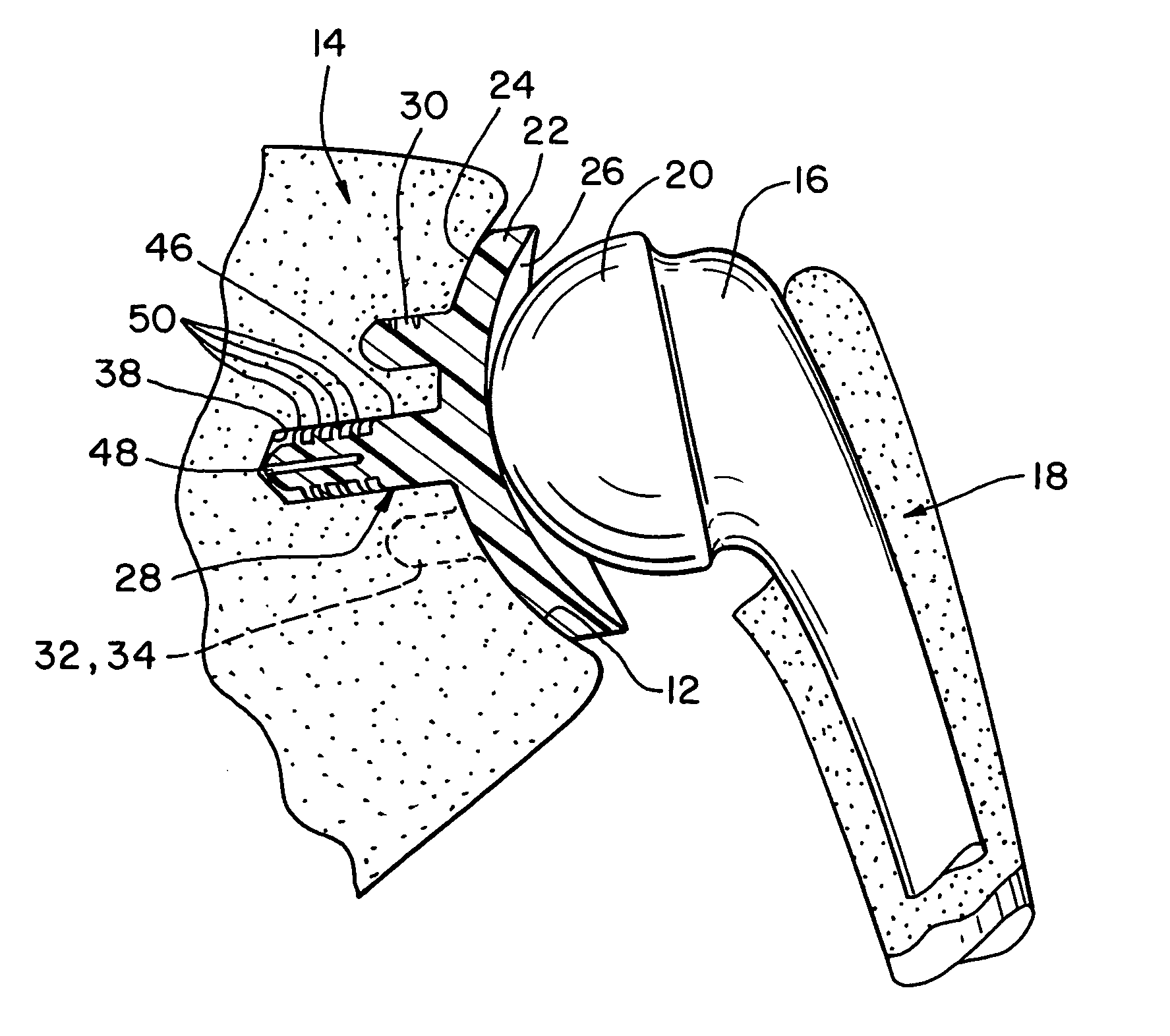
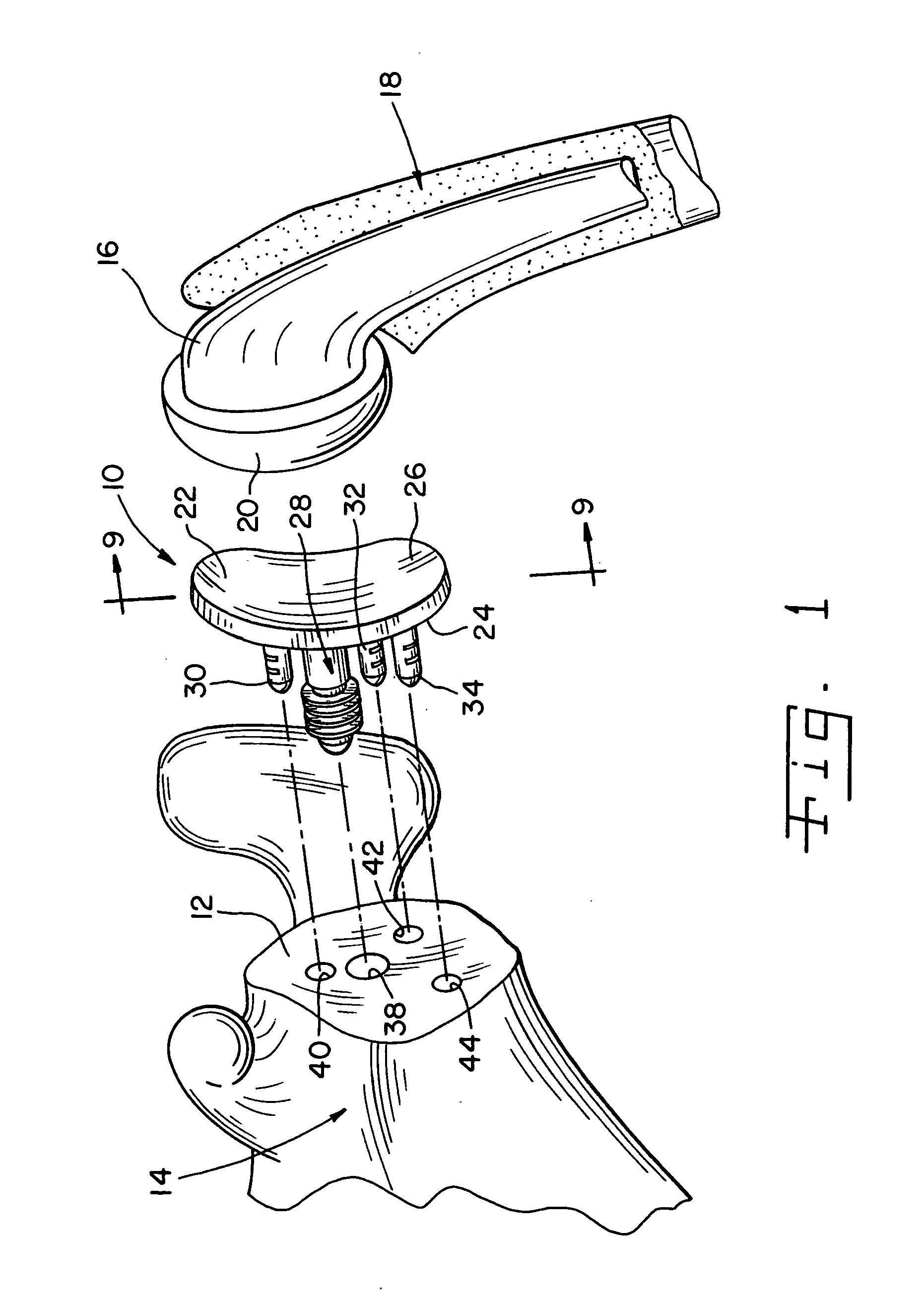
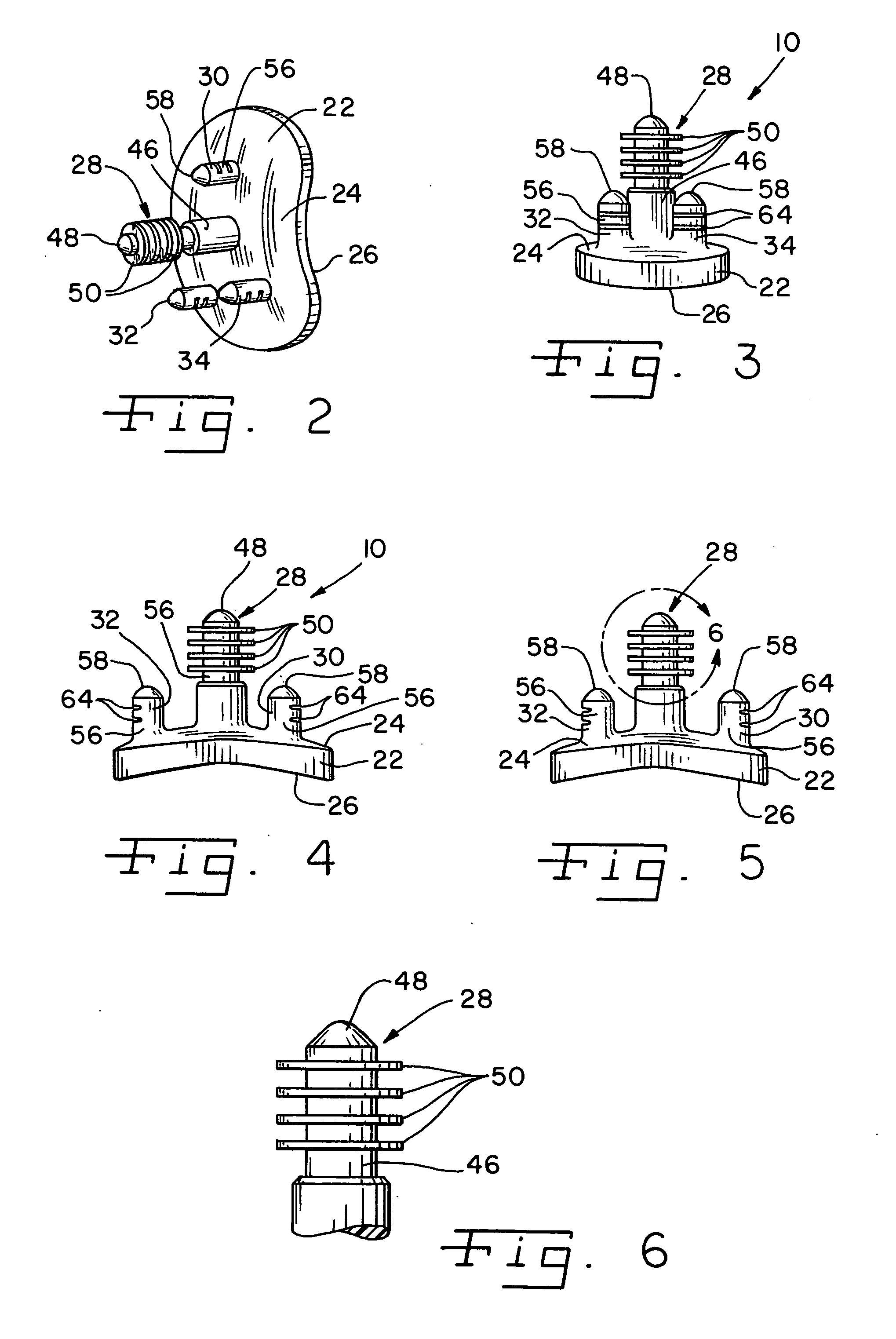
[0027] Referring now to FIG. 1, there is shown a glenoid component 10 located between a glenoid surface 12 of a scapula 14 and a humeral component 16. The humeral component 16 has been implanted or otherwise secured to a humerus 18. As shall be discussed below in greater detail, the glenoid component 10 is configured to be secured to the glenoid surface 12 of the scapula 14 without the use of bone cement in order to replace the natural glenoid surface 12 during a total shoulder replac...


PUM


Abstract

A medical procedure includes providing a prosthesis which includes (i) a body portion having a rear surface and a bearing surface, and (ii) an anchor peg including a shaft extending from the rear surface of the body portion, wherein the anchor peg includes a plurality of outwardly extending fins secured to the shaft, and further wherein the plurality of outwardly extending fins each possesses a first diameter. The medical procedure further includes creating an anchor hole in a natural bone, the anchor hole possessing a second diameter which is less than the first diameter. In addition, the method procedure includes positioning the anchor peg within the anchor hole so that each of the plurality of outwardly extending fins deforms so as to possess (i) a concave side which faces an open end of the anchor hole, and (ii) a convex side that faces a closed end of the anchor hole.

Description

[0001] This application is a continuation of co-pending application Ser. No. 09 / 802,150, filed on Mar. 8, 2001, which in turn claims priority to U.S. Provisional Application Ser. No. 60 / 190,391, entitled “Apparatus and Method for Securing a Cementless Glenoid Component to a Glenoid Surface of a Scapula”, filed on Mar. 17, 2000. The disclosure of each of the above-identified provisional and utility patent applications are hereby totally incorporated by reference in their entirety.TECHNICAL FIELD OF THE INVENTION [0002] The present invention relates generally to a glenoid component, and more particularly to an apparatus and method for securing a cementless glenoid component to a glenoid surface of a scapula. BACKGROUND OF THE INVENTION [0003] During the lifetime of a patient, it may be necessary to perform a total shoulder replacement procedure on the patient as a result of, for example, disease or trauma. In a total shoulder replacement procedure, a humeral component having a head po...

Claims


Application Information

Patent Timeline
Patent Type & Authority Applications(United States)
IPC IPC(8): A61F2/00A61F2/30A61F2/40A61F2/46
CPCA61F2/40A61F2250/0037A61F2/4081A61F2002/30224A61F2002/30326A61F2002/30606A61F2002/30822A61F2002/30841A61F2002/30881A61F2002/30884A61F2002/30891A61F2002/30892A61F2002/30957A61F2002/4018A61F2002/4631A61F2230/0069A61F2/4059
Inventor ROCKWOOD, CHARLES A. JR.WIRTH, MICHAEL A.CAMINO, THOMAS S.LONG, JACK F.ONDRLA, JEFFREY M.
Owner DEPUY PROD INC
Learn More