Method and apparatus for controlling brake-steer in an automotive vehicle in reverse

a technology for reverse steering and automotive vehicles, applied in the direction of braking systems, vehicle position/course/altitude control, instruments, etc., can solve the problems of increasing increasing the cost, complexity, warranty, maintenance costs and weight of the vehicle, and achieving low cost. , the effect of improving the turning radius of the vehicle in a reverse direction

a technology for reverse steering and automotive vehicles, applied in the direction of braking systems, vehicle position/course/altitude control, instruments, etc., can solve the problems of increasing increasing the cost, complexity, warranty, maintenance costs and weight of the vehicle, and achieving low cost. , the effect of improving the turning radius of the vehicle in a reverse direction

US20050209763A1Active Publication Date: 2005-09-22FORD GLOBAL TECH LLC

Image

  • Method and apparatus for controlling brake-steer in an automotive vehicle in reverse
  • Method and apparatus for controlling brake-steer in an automotive vehicle in reverse
  • Method and apparatus for controlling brake-steer in an automotive vehicle in reverse

Examples


Embodiment Construction

[0037] In the following figures the same reference numerals will be used to identify the same components. The various terms and values are set forth by way of example and are not meant to be limiting unless specifically set forth in a claim.

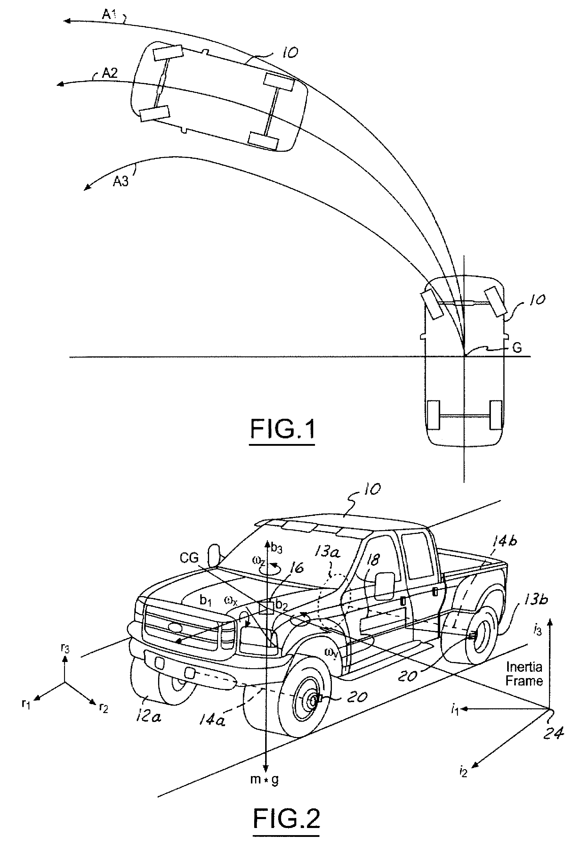
[0038] Referring now to FIG. 1, a vehicle 10 is illustrated traversing three paths. Path A1 is the path a vehicle travels without the invention. Path A2 is a path the vehicle 10 travels with brake-steer. Path A3 is a path the vehicle 10 travels with brake-steer and a controllable suspension component. As is shown, path A2 improves the turning radius over path A1. Path A3 has a reduced or improved turning radius compared to path A2.

[0039] The term brake-steer or brake-steering is used to describe changing a characteristic of the vehicle such as the turning radius or tracking of the vehicle using one or more brakes, the application of differential (positive or negative) torques, or a combination of the braking and differential torques. Positive t...


PUM


Abstract

A system and method of controlling an automotive vehicle includes generating a reverse direction signal corresponding to a reverse direction of the vehicle and generating brake-steer in response to the reverse direction signal.

Description

CROSS REFERENCE TO RELATED APPLICATIONS [0001] The present invention is related to U.S. Applications (Attorney Docket No. 81093807 / FGT-1902 PA) entitled “Control System for Brake-Steer Assisted Parking and Method Therefor”; (Attorney Docket No. 81093810 / FGT-1903 PA) entitled “Method and Apparatus of Controlling an Automotive Vehicle Using Brake-Steer as a Function of Steering Wheel Torque”; (Attorney Docket No. 81093816 / FGT-1904 PA) entitled “Method and Apparatus for Controlling an Automotive Vehicle Using Brake-Steer and Normal Load”; (Attorney Docket No. 81093821 / FGT-1906 PA) entitled “Method and Apparatus for Controlling Brake-Steer in an Automotive Vehicle in a Forward and Reverse Direction”; (Attorney Docket No. 81093822 / FGT-1907 PA) entitled “Method of Controlling an Automotive Vehicle Having a Trailer”; (Attorney Docket No. 81093824 / FGT-1908 PA) entitled Method of Controlling an Automotive Vehicle Having a Trailer Using Rear Axle Slip Angle”; (Attorney Docket No. 81093839 / FGT...

Claims


Application Information

Patent Timeline
22 Sep 2005
Publication
US20050209763A1
IPC
B60T7/12; B60T8/1755; B60T8/24; B60T11/21; B60W10/18; B60W10/20; B62D6/00; B62D9/00; B62D11/08; B62D15/02; G06F7/00
CPC
B60T8/1755; B60T11/21; B60T2230/06; B60T2230/08; B60T2260/02; Y10T477/80; B60W10/20; B60W30/045
Inventors
OFFERLE, TIMOTHY G.; TSENG, HONGTEI E.