Method and apparatus for determining monitoring locations in distributed systems

a distributed system and monitoring location technology, applied in the field of monitoring distributed systems, can solve the problems of high computation overhead, failure to propagate in the network, inability of a client to communicate with a server, etc., and achieve the effect of reducing the number of detectable events

Active Publication Date: 2005-09-22
VMWARE INC
View PDF3 Cites 64 Cited by
  • Summary
  • Abstract
  • Description
  • Claims
  • Application Information

AI Technical Summary

Benefits of technology

[0022] A method and system for determining the number and location of monitoring entities in a distributed system is disclosed. The method comprising the steps of automatically generating a causality mapping model of the dependences between causing events at the nodes of the distributed system and the detectable events associated with a subset of the nodes, the model suitable for representing the execution of at least one system operation, reduci...

Problems solved by technology

Such failure can propagate in the network (application) and manifest symptoms detected by the monitors such as the inability of a client to communicate with a server, for example.
It is, however, costly and results in high computation overhead as high volume of traffic is needed to relay all the events that the monitoring entities detect or observe to t...

Method used


Image

  • Method and apparatus for determining monitoring locations in distributed systems
  • Method and apparatus for determining monitoring locations in distributed systems
  • Method and apparatus for determining monitoring locations in distributed systems

Examples


Embodiment Construction

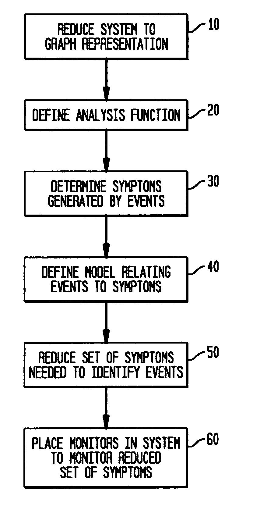
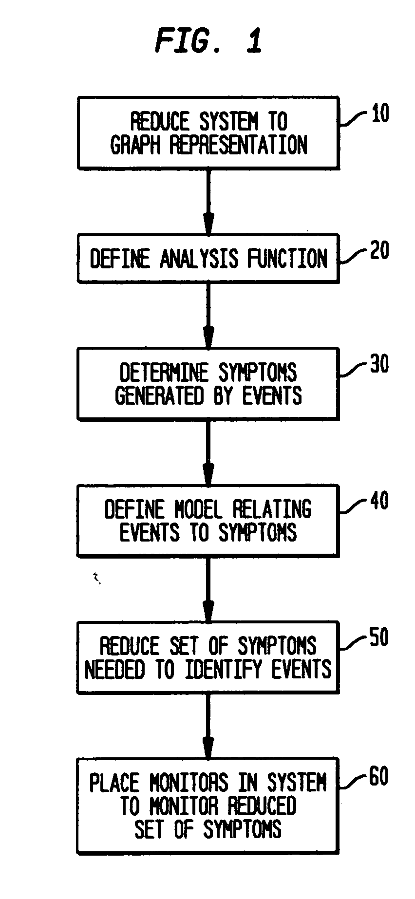
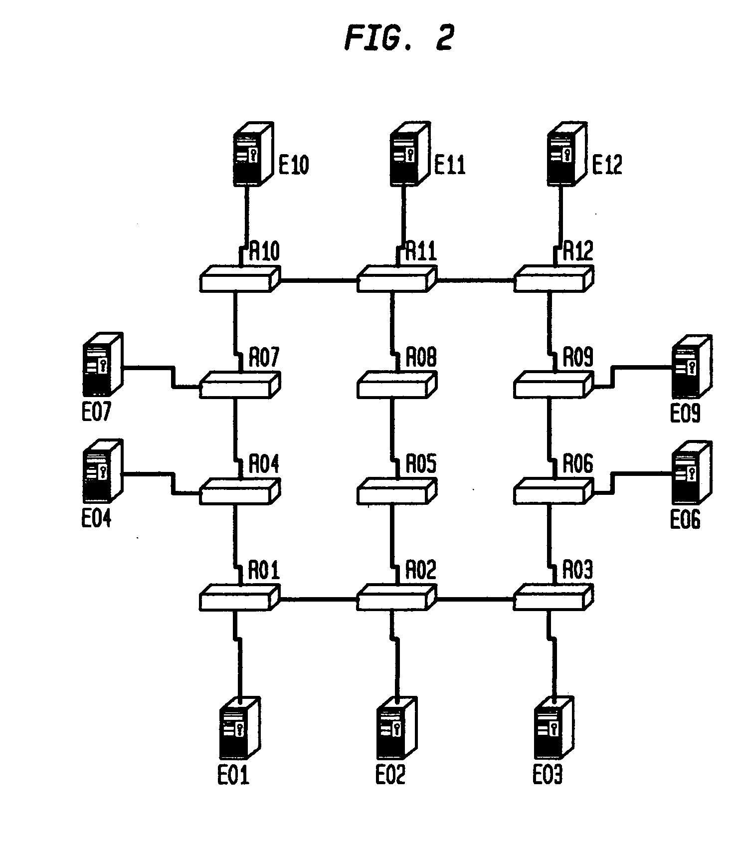
[0041] In accordance with the principles of the invention, a distributed system management task may be reduced to managing a known property of a graph G or other representation of the network. The graph representation of the network includes nodes that may represent a number of hardware or software system components and the links between nodes that may represent a number of relationships or dependencies among the nodes. For example, a represented or managed system may be a network of routers connected via physical links or virtual connections or a distributed application with components executing at different hosts or servers. In the latter case, the links can represent the dependencies between the application and the hosting system, between the application components themselves, and / or between the hosting systems themselves. The graph properties to be monitored can include, but are not limited to, node failures, link failures, node processing overload, link traffic congestion, appl...


PUM


Abstract

A method and apparatus for determining the number and location of monitoring entities in a distributed system is disclosed. The method comprising the steps of automatically generating a causality mapping model of the dependences between causing events at the nodes of the distributed system and the detectable events associated with a subset of the nodes, the model suitable for representing the execution of at least one system operation, reducing the number of detectable events in the model, wherein the reduced number of detectable events is suitable for substantially representing the execution of the at least one system operation; and placing at least one of the at least one monitoring entities at selected ones of the nodes associated with the detectable events in the reduced model. In another aspect, the processing described herein is in the form of a computer-readable medium suitable for providing instruction to a computer or processing system for executing the processing claimed.

Description

CLAIM OF PRIORITY [0001] This application claims the benefit, pursuant to 35 USC §119(e), of the earlier filing date of U.S. Provisional Patent Application Ser. No. 60 / 552,559, entitled Method and Apparatus for Monitoring Distributed Systems,” filed in the US Patent Office on Mar. 12, 2004, the contents of which are incorporated by reference, herein. RELATED APPLICATIONS [0002] This application is related to commonly-owned: U.S. patent application Ser. No. ______, entitled “Method and Apparatus for Determining Causality Mapping of Distributed Systems, concurrently filed, the contents of which are incorporated by reference herein.BACKGROUND OF THE INVENTION [0003] 1. Field of the Invention [0004] The present application relates to monitoring distributed systems for monitoring, analysis and management and more particularly to reducing the number and determining the appropriate location of monitors used for system monitoring, analysis and management operations. [0005] 2. Description of...

Claims


Application Information

Patent Timeline
IPC IPC(8): G06F9/44G06F9/46G06F15/173H04L12/24H04L12/26
CPCG06F11/3006H04L43/12H04L41/0613G06F11/3096
Inventor FLORISSI, DANILOFLORISSI, PATRICIA GOMES SOARESKLEERS, UDIKLIGER, SHMUELYARDENI, EYALYEMINI, YECHIAM
Owner VMWARE INC
Why Eureka
Try Eureka