
Method and system for multi-user channel allocation for a multi-channel analyzer

a multi-channel analyzer and multi-user technology, applied in the field of multi-user channel allocation for multi-channel analyzers, can solve the problems of not being able to easily integrate the data from multiple ones of the analyzer, not working well to track down problems or optimize the communication interface between multiple computing devices in a large fibre channel network, and not being able to achieve the optimization of communication interfaces, reducing the amount of data, and enhancing the analysis of data captured by the integrated multi-channel analyz

Inactive Publication Date: 2005-09-22
VIAVI SOLUTIONS INC
View PDF5 Cites 16 Cited by
  • Summary
  • Abstract
  • Description
  • Claims
  • Application Information

AI Technical Summary

Benefits of technology

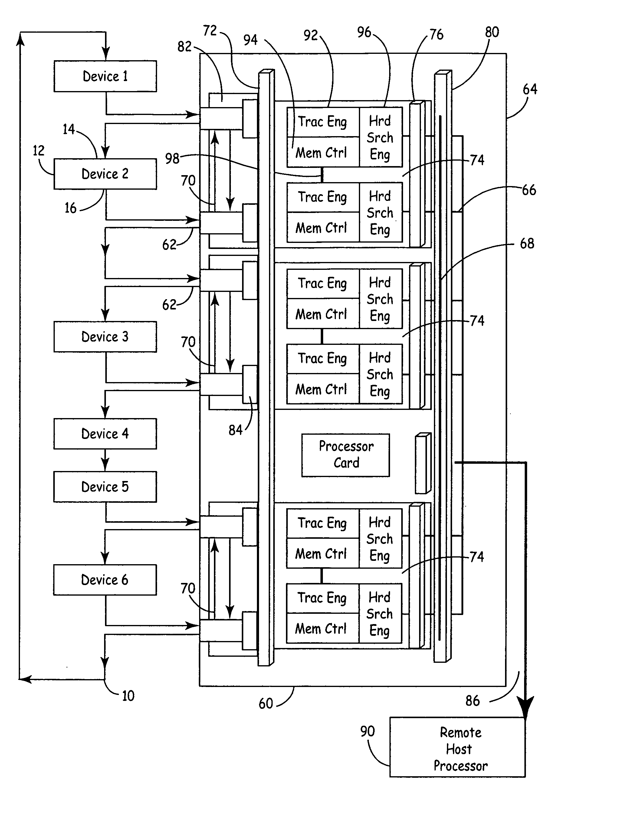
[0010] In the preferred embodiment, the multi-channel analyzer is an integrated multi-channel Fibre Channel analyzer that provides coordinated and cooperative triggering and capture of data across multiple channels in a Fibre Channel network. The integrated multi-channel analyzer accommodates up to sixteen separate analyzer channels in a single cabinet. Each analyzer channel is comprised of an input port connection to the Fibre Channel network, a trace buffer memory that captures data and logic circuitry that controls the operation of the trace buffer memory in response to a status condition. A high-speed status bus is connected to each analyzer channel and propagates the status conditions of each analyzer channel to all other analyzer channels. In this way, the integrated multi-channel analyzer allows for distributive control over triggering decisions across multiple analyzer channels, and also allows for multi-level triggering where different conditions may be detected by different analyzer channels.
[0011] Analysis of the data captured by the integrated multi-channel analyzer is enhanced by a processor resident in the cabinet that is connected by a data / control bus to each analyzer channel and its associated trace buffer memory. The resident processor receives high level commands from a remote host processor and coordinates the way in which the analyzer channels are configured to monitor the Fibre Channel network. Once trace data is captured in one or more of the trace buffer memories, the resident processor coordinates the transfer of relevant portions of the trace data to the remote host processor. To reduce the amount of data that must be transferred to the remote host processor, each analyzer channel preferably includes a hardware search engine that can quickly and efficiently identify relevant data patterns in the trace buffer memory. Once the trace data has been captured in the trace buffer memories, the resident processor initiates a time indexing routine that uses the hardware search engine in each analyzer channel to index the trace data for that analyzer channel.
[0012] Because all of the trace data in all of the analyzer channels has utilized a common clock to establish the time-stamping, the resident processor can quickly identify and download data segments from the trace buffer memories of different analyzer channels to the remote host processor without the need for an intermediate step of time-stamp synchronizing this data. In addition, the resident processor is capable of performing initial analysis on the trace data internal to the multi-channel analyzer. These distilled results of the analysis may be communicated from the resident processor to the remote host processor over a relatively small bandwidth communication channel, such as an Ethernet connection, without the need for a large bandwidth communication channel in order to download massive amounts of raw data to the host processor as was required in the prior art. Moreover, the use of a common clock for storing the trace data removes the burden on the host processor of time-stamp collating this massive amount of raw data based only on the coordination of periodic sync pulses as provided for in the prior art.
[0013] Preferably, the analyzer channels of the multi-channel analyzer are configured with two analyzer channels per analysis logic card with a local bus on the analysis logic card providing cross access between the input port and trace buffer memories of both analyzer channels. The logic circuitry of each analyzer channel also preferably comprises a pair of field programmable gate arrays that implement a trac engine that controls triggering and operation of the analyzer channel and a memory control / filtering function gate array that controls memory access and filtering functions performed by the analyzer channel. The trac engine is preferably comprised of a pair of trac processors that each executes a unique set of analyzer instructions downloaded from the resident processor. Unlike existing analyzers, the trac engine provides for enhanced flexibility by allowing the analyzer instructions to be assembled and organized in such a manner as to allocate varying amounts of the functionality of each trac processor to monitor for different conditions. The utilization of two trac processors per trac engine allows each analyzer channel to create more complex multi-level triggering conditions.
[0014] In a preferred embodiment, each analysis logic card is plugged into both a frontplane and a backplane. The frontplane interfaces the input port connection to the Fibre Channel network with the analyzer channel. The input port connection is preferably a module designed to interface to the particular Fibre Channel environment through industry standard converters. The backplane interfaces the analyzer channel with the high-speed status bus and the data / control bus and on through to the resident processor. The backplane also provides a system-wide clock that is distributed to each analyzer channel, thereby solving the problem of the lack of a common time base which confronts the prior art when multiple analyzers are hand-wired together using only simplistic and trigger-out and trigger-in signals. As a result, it is not necessary for the multi-channel analyzer of the present invention to time-stamp collate trace data from different analyzers.

Problems solved by technology

Analyzers designed for high-speed interfaces, such as the Fibre Channel protocol, must overcome significant technical challenges due to the extremely high bandwidth and high data transfer rates that are supported by the Fibre Channel communication interface.
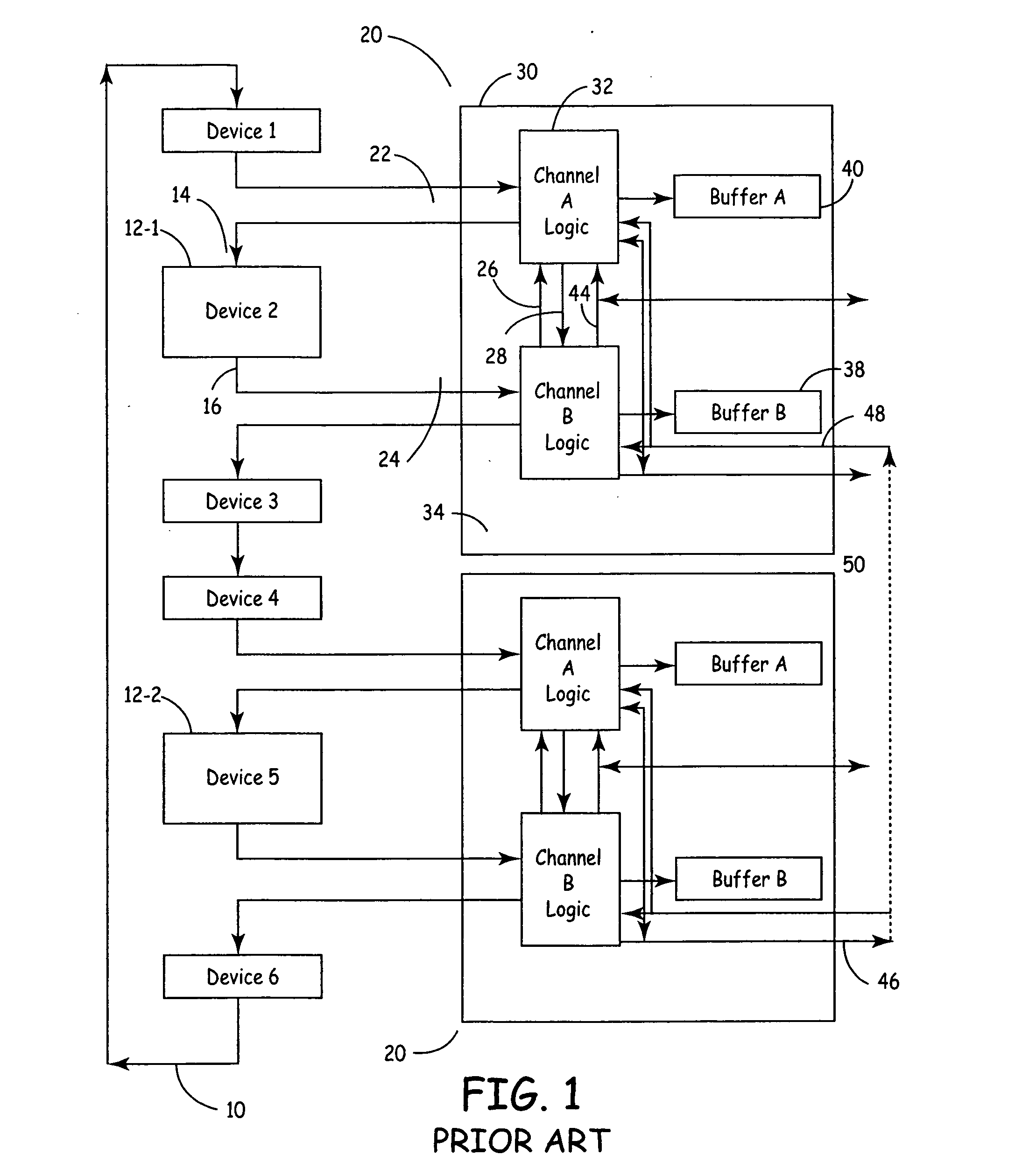
While existing Fibre Channel analyzers work well at debugging communication protocol problems at the particular device to which the analyzer is connected, they do not work well to track down problems or to optimize the communication interface across multiple computing devices in a large Fibre Channel network.
Because of the existing limitation in current Fibre Channel analyzers of only being able to connect to the input and output ports of a single device, analysis of a problem in a large Fibre Channel network requires the use of multiple analyzers.
Unfortunately, there is no convenient way of integrating the data from multiple ones of these analyzers in order to make the analysis and presentation of data about such a problem a simple or straightforward matter.
Although it is possible to arrange multiple analyzers in this manner, it is difficult and time consuming to set up because the analyzers are not designed for any type of coordinated arrangement.
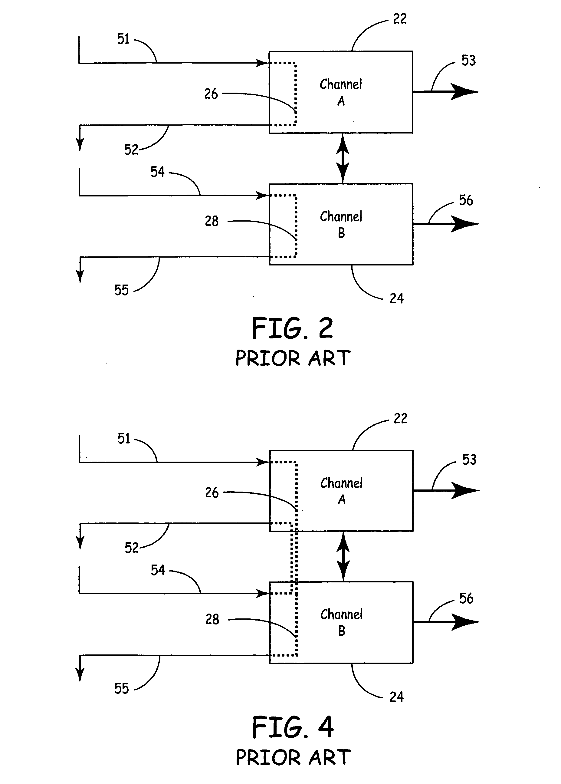
Moreover, it has been discovered that the kinds of problems encountered in large complex multi-device Fibre Channel communication networks are very often too complicated for such a simplistic arrangement as having a trigger out-sync signal of one analyzer connected to the trigger in-sync signal of a second analyzer.
For example, in Fibre Channel networks that allow for multiple paths over which data packets may travel between a source and destination, monitoring the actual path that any given data packet may be taking becomes less and less predictable as the complexity of the network interconnections increases.

Method used


Image

  • Method and system for multi-user channel allocation for a multi-channel analyzer
  • Method and system for multi-user channel allocation for a multi-channel analyzer
  • Method and system for multi-user channel allocation for a multi-channel analyzer

Examples


examples

[0215] 0000: word match if (match byte 3) and (match byte 2) and (match byte 1) and (match byte 0). [0216] 0100: word match if (match byte 3) and (NO match byte 2) and (match byte 1) and (match byte 0). [0217] 1111: word match if (NO match byte 3) and (NO match byte 2) and (NO match byte 1) and (NO match byte 0).

abort_config: (8 bits) [0218] bit 0: store a new qualifier z. [0219] bit 1: new qualifier z has one-frame scope.

Counters

[0220] There may be up to 24 counters: 8 time counters, 8 loop counters, and 8 word counters. Each counter behaves differently, but all share some characteristics: [0221] Counters always count up. [0222] Counters have one initialization value which is loaded every time the counter is reset. [0223] Counters will output a “done” signal when they roll over from the highest possible count to zero. [0224] To implement a countdown, the initialization value should be set to a negative number. Then the done signal will be asserted as the counter rolls over to ...


PUM


Abstract

Multiple channels of a multi-channel analyzer are allocated among multiple users such that each user can initiate and retrieve the results of separate diagnostic sessions or strategies. Each analyzer channel of the multi-channel analyzer includes an input connection port, a trace buffer memory and logic circuitry. The input connection port of each analyzer channel is operably connected to a unique node in the communication network. A host processor connected to each analyzer channel assigns ownership of a unique set of analyzer channels to at least two different users such that each user can initiate separate traces that are simultaneously established on the communication network. The logic circuitry in each analyzer channel monitors frame data on the connection port at each node in accordance with a set of instructions established by the user assigned to the analyzer channel for that node, and the traces are captured in response to the set of instructions for each analyzer channel such that each user retrieves only the results of the analyzer channels assigned to that user.

Description

RELATED APPLICATIONS [0001] This application is a divisional of application Ser. No. 09 / 850,673 filed May 7, 2001, which in turn is a continuation-in-part of co-pending application Ser. No. 09 / 294,935 filed Apr. 19, 1999, and also claims priority to provisional Application No. 60 / 202,327, filed May 5, 2000.FIELD OF THE INVENTION [0002] The present invention relates generally to the field of diagnostic equipment, testers, and analyzers for use with communication interfaces among computing devices. More specifically, the present invention relates to a system for allocating multiple channels among multiple users for a multi-channel analyzer such that each user can initiate and retrieve the results of separate diagnostic sessions or strategies. BACKGROUND OF THE INVENTION [0003] Analyzers are used as diagnostic and testing tools at various stages of the development, integration and maintenance of electronic computing devices. Typically, an analyzer is designed for use with a particular ...

Claims


Application Information

Patent Timeline
Patent Type & Authority Applications(United States)
IPC IPC(8): G01R31/28G06F11/25H04L12/26
CPCH04L43/026Y02B60/33H04L43/18Y02D30/50
Inventor MASTRO, JEFFBUCHER, STEVEN
Owner VIAVI SOLUTIONS INC
Learn More