Aerodynamic orbit inclination control

a technology of inclination control and orbit, applied in the field of aerodynamic orbit inclination control, can solve the problems of limited ability of conventional propulsion systems to effect major inclination angle changes, and achieve the effects of reducing the amount of fuel, and different orbit inclination angles

Inactive Publication Date: 2005-09-29
AEROASTRO
View PDF24 Cites 17 Cited by
  • Summary
  • Abstract
  • Description
  • Claims
  • Application Information

AI Technical Summary

Benefits of technology

[0004] Although a high-energy to low-energy orbit change as taught by the above inventions provides for a substantial reduction in the amount of fuel required to be carried by the satellite, or the orbit transfer vehicle, fuel is still required during the maneuvering process to change the inclination angle of the satellite's orbit, if the inclination angle provided by the launch vehicle (the insertion inclination) is different from the inclination of the target orbit.
[0005] Additionally, conventional propulsion systems are limited in their ability to effect major inclination angle changes. For example, an orbit transfer vehicle with conventional propulsion system would be required to allocate at least half its mass to achieve a twenty five degree change in inclination angles. For this reason, different launch locations are required to achieve substantially different orbit inclination angles.
[0006] It is an object of this invention to minimize the amount of fuel required to maneuver a satellite into its target orbit, and particularly the amount of fuel required to change the inclination angle of an orbiting object. It is a further object of this invention to reduce the amount of fuel that an orbit transfer vehicle needs to carry. It is a further object of this invention to provide a means for achieving changes in inclination angles of more than forty five degrees.

Problems solved by technology

Additionally, conventional propulsion systems are limited in their ability to effect major inclination angle changes.

Method used


Image

  • Aerodynamic orbit inclination control
  • Aerodynamic orbit inclination control
  • Aerodynamic orbit inclination control

Examples


Embodiment Construction

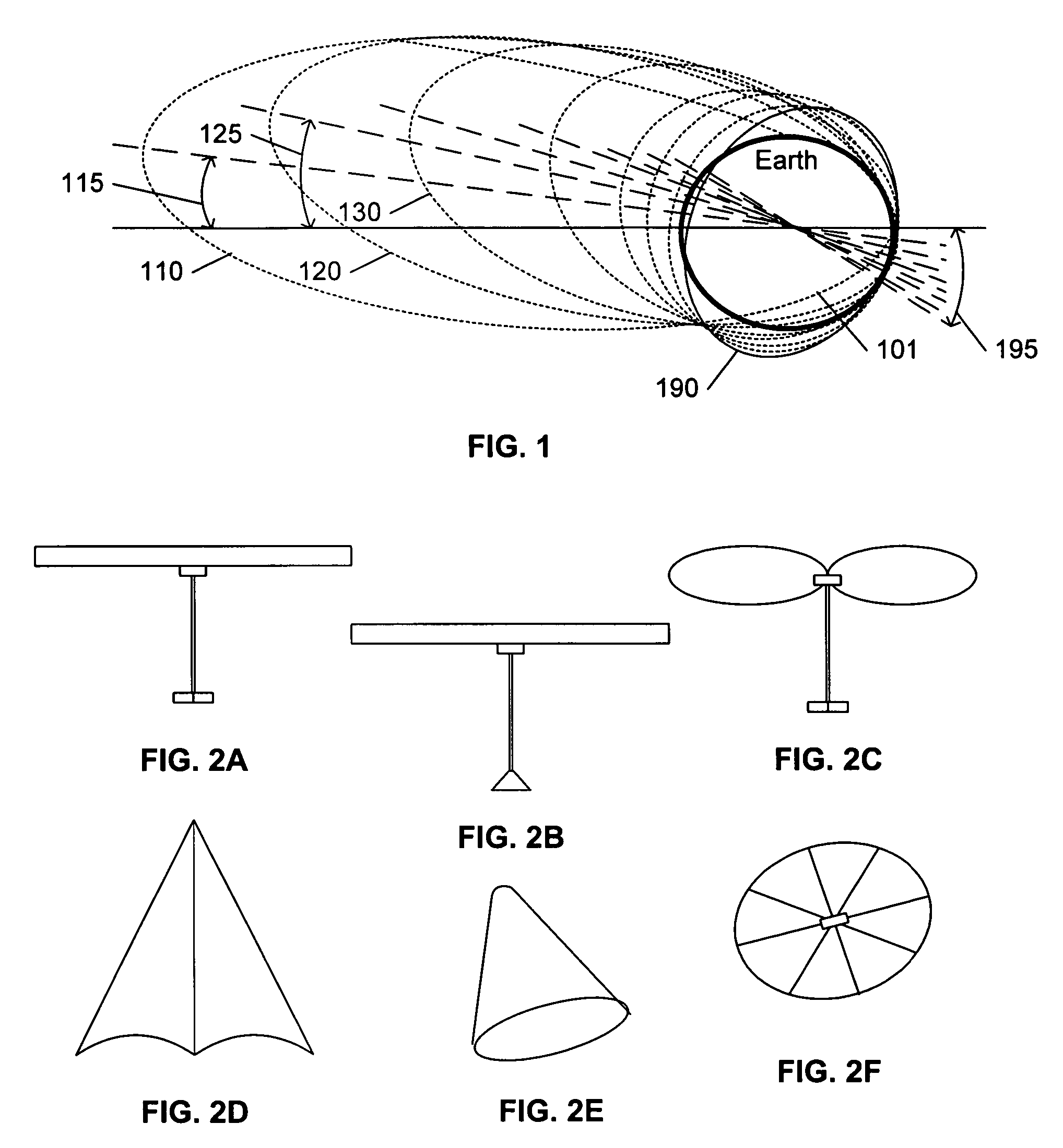
[0014] The invention is presented using the paradigm of a conventional launch of an orbit transfer vehicle into a geosynchronous orbit (GEO) and a subsequent maneuvering of the orbit transfer vehicle into a target low earth orbit (LEO) at a given inclination angle. However, one of ordinary skill in the art will recognize that the invention is not limited to this example. For example, in surveillance or other applications, the transfer vehicle may remain at a high-energy orbit indefinitely, and then employ the techniques of this invention to maneuver to a target inclination in order to overpass select regions of the earth when a need arises, and remain there until a new need arises. Each maneuver results in a lower-energy orbit, but this as-needed maneuvering can be repeated until the energy is insufficient to provide the desired amount of inclination change. Similarly, propulsion systems can be provided to offset and / or restore the loss of orbit energy. In like manner, although the ...


PUM


Abstract

A method and system for deploying a spacecraft into a target orbit includes the use of controllable aerodynamic surfaces that can be deployed to facilitate a change in the inclination angle of the trajectory of the spacecraft. In a typical embodiment, the spacecraft includes an orbit transfer vehicle containing the aerodynamic structure, and a satellite that is to be placed into the target orbit. The spacecraft is launched to a higher-energy orbit than the target orbit, and the energy released by traveling to the target orbit is used to change the inclination angle. After entering a transfer orbit that includes a passage through the upper limits of the earth's atmosphere, the orbit transfer vehicle deploys the aerodynamic structure, and controls the aerodynamic surfaces of the structure to induce lift forces that alter its inclination angle each time the vehicle enters the atmosphere.

Description

[0001] This application claims the benefit of U.S. Provisional Patent Application 60 / 551,462, filed 9 Mar. 2004.BACKGROUND AND SUMMARY OF THE INVENTION [0002] This invention relates to the field of aerospace, and in particular to an orbit transfer vehicle that uses aerodynamics to achieve a desired orbit inclination angle. [0003] U.S. Pat. No. 6,286,787 “SMALL SATELLITE GEO-TO-LEO ORBIT TRANSFER VEHICLE”, issued 11 Sep. 2001 to Richard Fleeter, U.S. Pat. No. 6,409,124 “HIGH-ENERGY TO LOW-ENERGY ORBIT TRANSFER VEHICLE”, issued 25 Jun. 2002 to Richard Fleeter, and U.S. Pat. No. 6,550,720 “AEROBRAKING ORBIT TRANSFER VEHICLE”, issued 22 Apr. 2003 to Richard Fleeter, Daniel B. DeBra, Paul Gloyer, Zeno Wahl, and David Goldstein, each incorporated by reference herein, teach the placement of a satellite into target orbit by first launching the satellite into a transfer orbit having a substantially higher potential energy than the target orbit, then decreasing the energy of the satellite. In...

Claims


Application Information

Patent Timeline
Patent Type & Authority Applications(United States)
IPC IPC(8): B64G1/00B64G1/24B64G1/62
CPCB64G1/007B64G1/62B64G1/24B64G1/244B64G1/2427
Inventor GLOYER, PAULVANEK, THOMAS W.PEDLIKIN, JOEL
Owner AEROASTRO
Why Eureka
Try Eureka