

Display apparatus
a display apparatus and display technology, applied in lighting and heating apparatus, identification means, instruments, etc., can solve problems such as lack of stereoscopic visual effects, and achieve the effects of simple structure, enhanced stereoscopic and innovative visual effects, and simple structur
- Summary
- Abstract
- Description
- Claims
- Application Information
AI Technical Summary
Benefits of technology
Problems solved by technology
Method used
Image

Examples
first embodiment
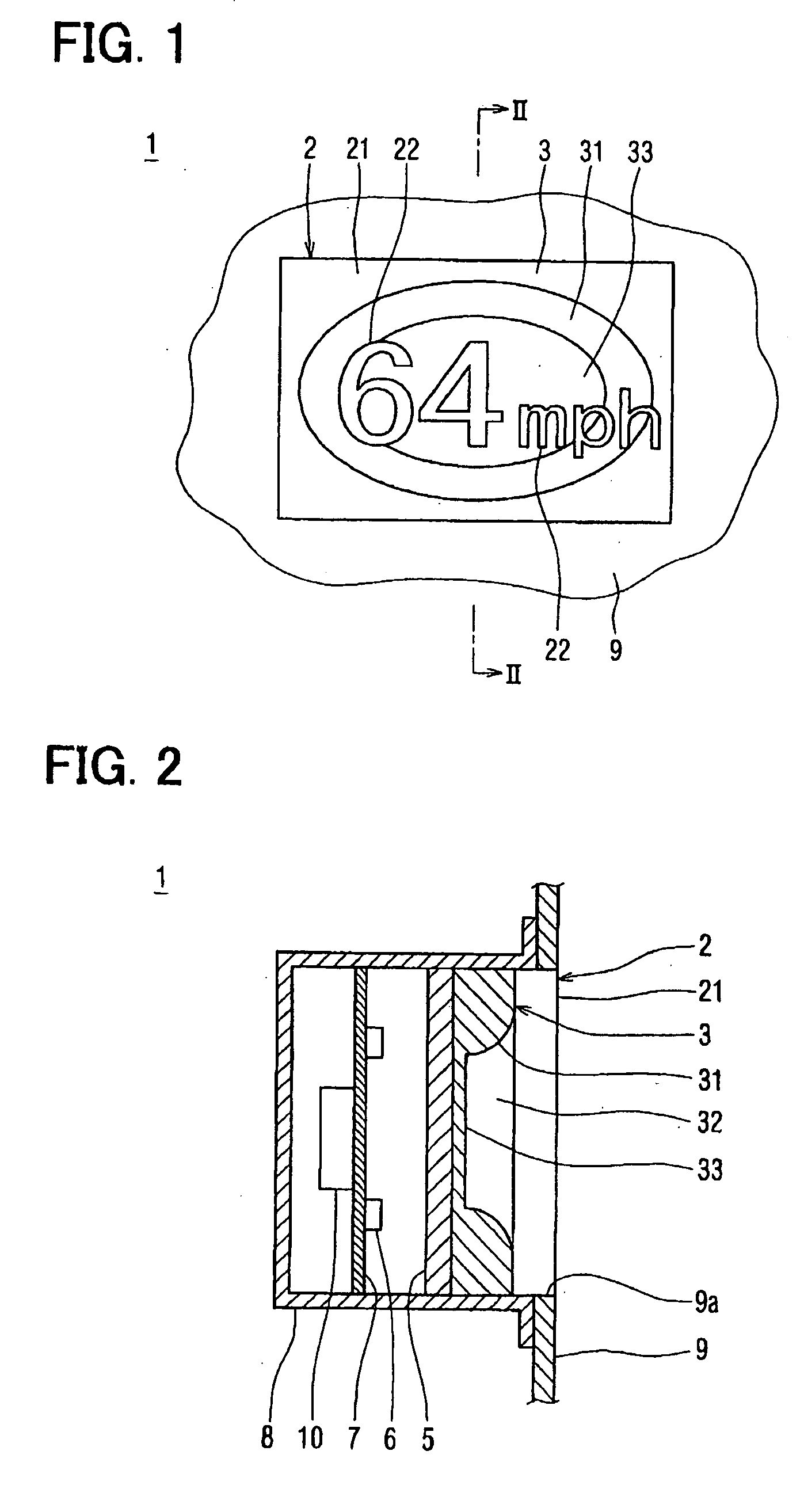
[0052] A structure of the combination meter 1 will be described below.
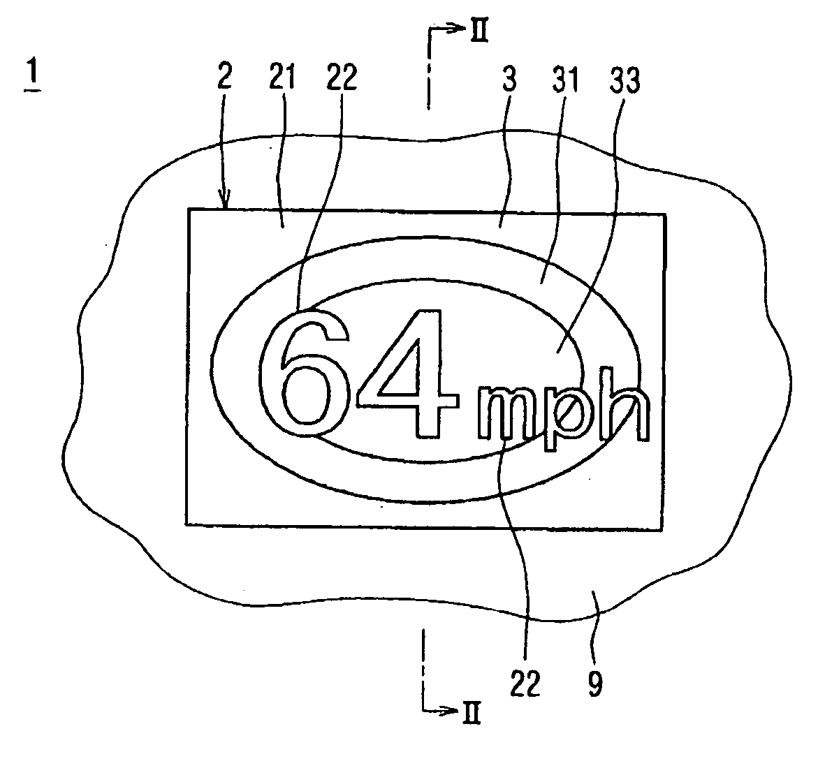
[0053] As shown in FIG. 2, the liquid crystal panel 2 of the transmissive liquid crystal display device is attached by fitting it into an opening 9a provided in a faceplate 9 of the combination meter 1. In FIG. 2, the driver's seat is assumed to be on the right-hand side so that the combination meter 1 is visible from the right-hand side. The liquid crystal panel 2 according to the first embodiment is used as a so-called digital speed meter that numerically displays the traveling speed of the automobile as shown in FIG. 1.
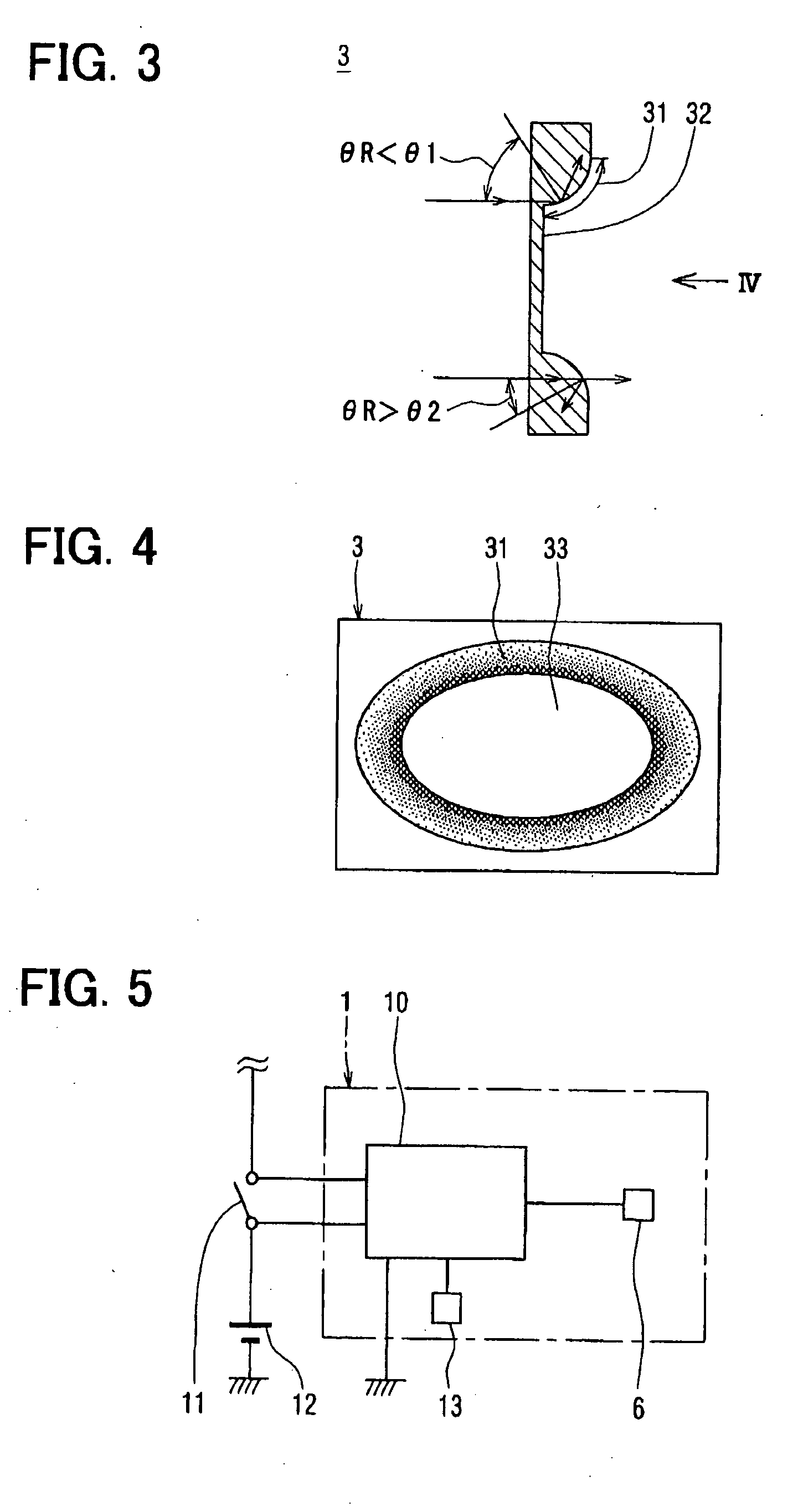
[0054] In the rear of the liquid crystal panel 2, which is on the left-hand side in FIG. 2, a prism plate 3 of a light transmittance control means is disposed. The prism plate 3 is formed of a clear and colorless resin such as polycarbonate resin, acrylic resin, or the like. The prism plate 3 has a recess 32 formed along a sightline, which originates to the right and looks to the left of the de...
second embodiment
[0075]FIG. 6 is a cross-sectional view illustrating a combination meter 1 according to the present invention.
[0076] The combination meter 1 according to the second embodiment differs from the one according to the first embodiment in the position of the prism plate 3. That is, in the combination meter 1 according to the second embodiment, as shown in FIG. 6, the prism plate 3 is disposed in front of the liquid crystal panel 2 or on the viewer side.
[0077] In this case, as in the combination meter 1 according to the first embodiment, the sidewall 31 in the prism plate 3 is visible in the bright background with uniform luminance as an elliptical ring having a certain width, which is dark in the inner periphery and becomes gradually brighter toward the outer periphery.
[0078] The liquid panel 2 is viewed as if it were disposed at the deepest position or at the furthest position from the viewer in the space with depth created by an effect of the prism plate 3 in the visible direction.
[0...
third embodiment
[0080]FIG. 7 is a cross-sectional view illustrating the combination meter 1 according to the present invention.
[0081] The combination meter 1 according to the third embodiment differs from the one according to the first embodiment in the shape of the prism plate 3. That is, in the combination meter 1 according to the third embodiment, the bottom area 33 in the prism plate 3 according to the first embodiment is removed to form a through-hole 34 as shown in FIG. 7.
[0082] In this case, as in the combination meter 1 according to the first embodiment, the sidewall 31 in the prism plate 3 is visible in the bright background with uniform luminance as an elliptical ring having a certain width, which is dark in the inner periphery and becomes gradually brighter toward the outer periphery.
[0083] Accordingly, when the viewer sees the combination meter 1 according to the third embodiment, the background area of the liquid crystal panel 2 looks as if it becomes more distant from the viewer fro...
PUM
| Property | Measurement | Unit |
|---|---|---|
| transmittance | aaaaa | aaaaa |
| incident angle | aaaaa | aaaaa |
| light transmittance | aaaaa | aaaaa |
Abstract
Description
Claims
Application Information