Self light emitting display module, electronic equipment into which the same module is loaded, and inspection method of defect state in the same module

a self-lighting display module and display module technology, applied in the direction of identification means, instruments, static indicating devices, etc., can solve the problems of preventing the transmission of error-prone display information, unable to determine whether a displayed figure is “0” or “8”, and developing serious problems

Inactive Publication Date: 2005-09-29
TOHOKU PIONEER CORP
View PDF4 Cites 13 Cited by
  • Summary
  • Abstract
  • Description
  • Claims
  • Application Information

AI Technical Summary

Benefits of technology

[0010] The present invention has been developed as attention to the above-described realistic problems has been paid, and it is an object of the present invention to provide a self light emitting display module which is provided with a detection means which can inspect whether or n

Problems solved by technology

For example, regarding injection equipment for a medicine or the like, in the case where a bright leak phenomenon occurs in the scan direction on a portion displaying figures showing an injection amount, a problem that whether a displayed figure is “0” or “8” cannot be determined may occur.
A problem which may occur is that pixels of a part on which a decimal point is displayed are not lit so that the place for the figures is erroneously displayed so that the figures are read while this is not being noticed or the like.
It is extremely dangerous for a user to keep using the above-described equipment while perceiving display in a troubled state being normal, and it is needless to say that such a state may develop a serious problem.
In a case where the evaluation device disclosed

Method used


Image

  • Self light emitting display module, electronic equipment into which the same module is loaded, and inspection method of defect state in the same module
  • Self light emitting display module, electronic equipment into which the same module is loaded, and inspection method of defect state in the same module
  • Self light emitting display module, electronic equipment into which the same module is loaded, and inspection method of defect state in the same module

Examples


Embodiment Construction

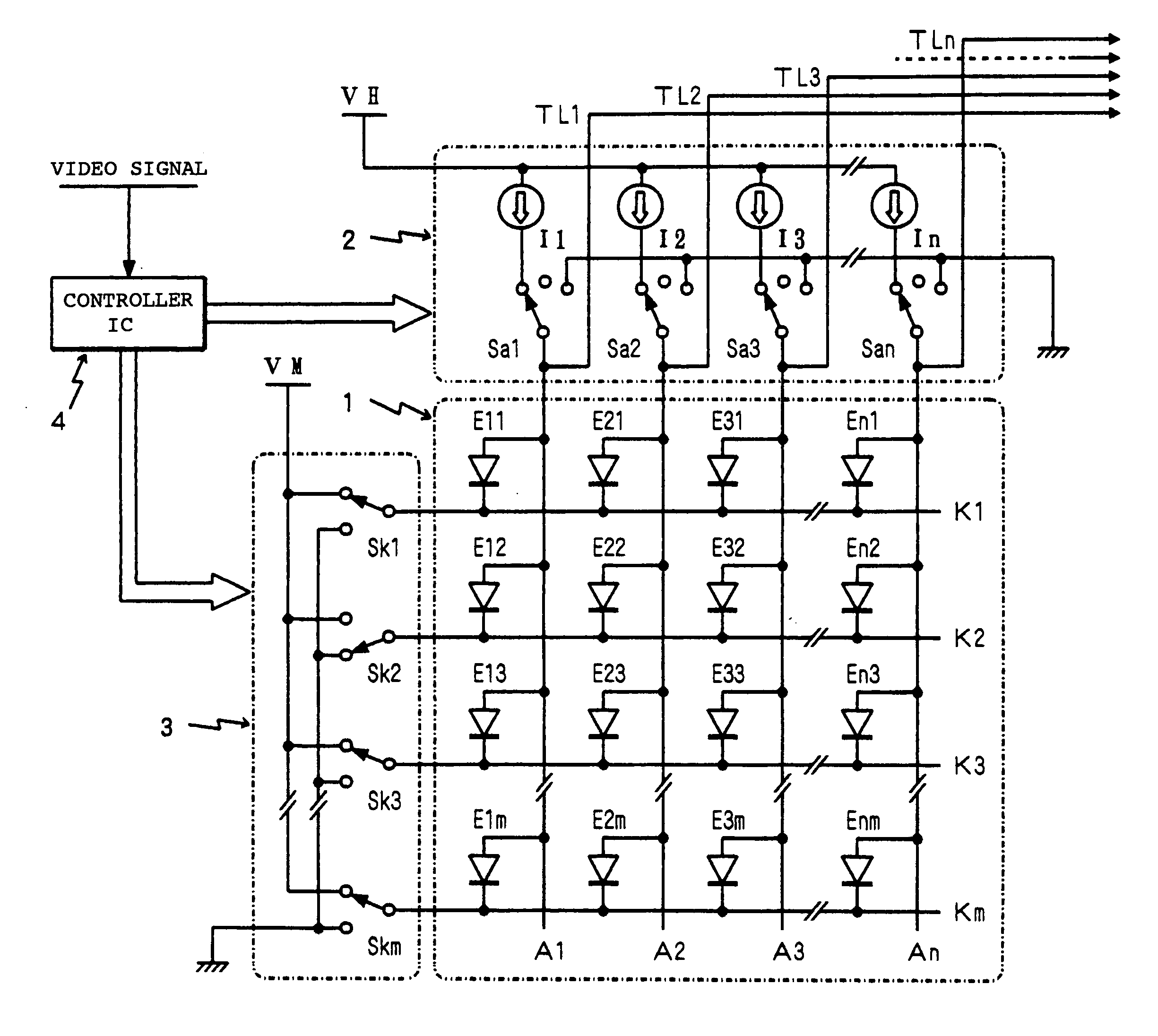
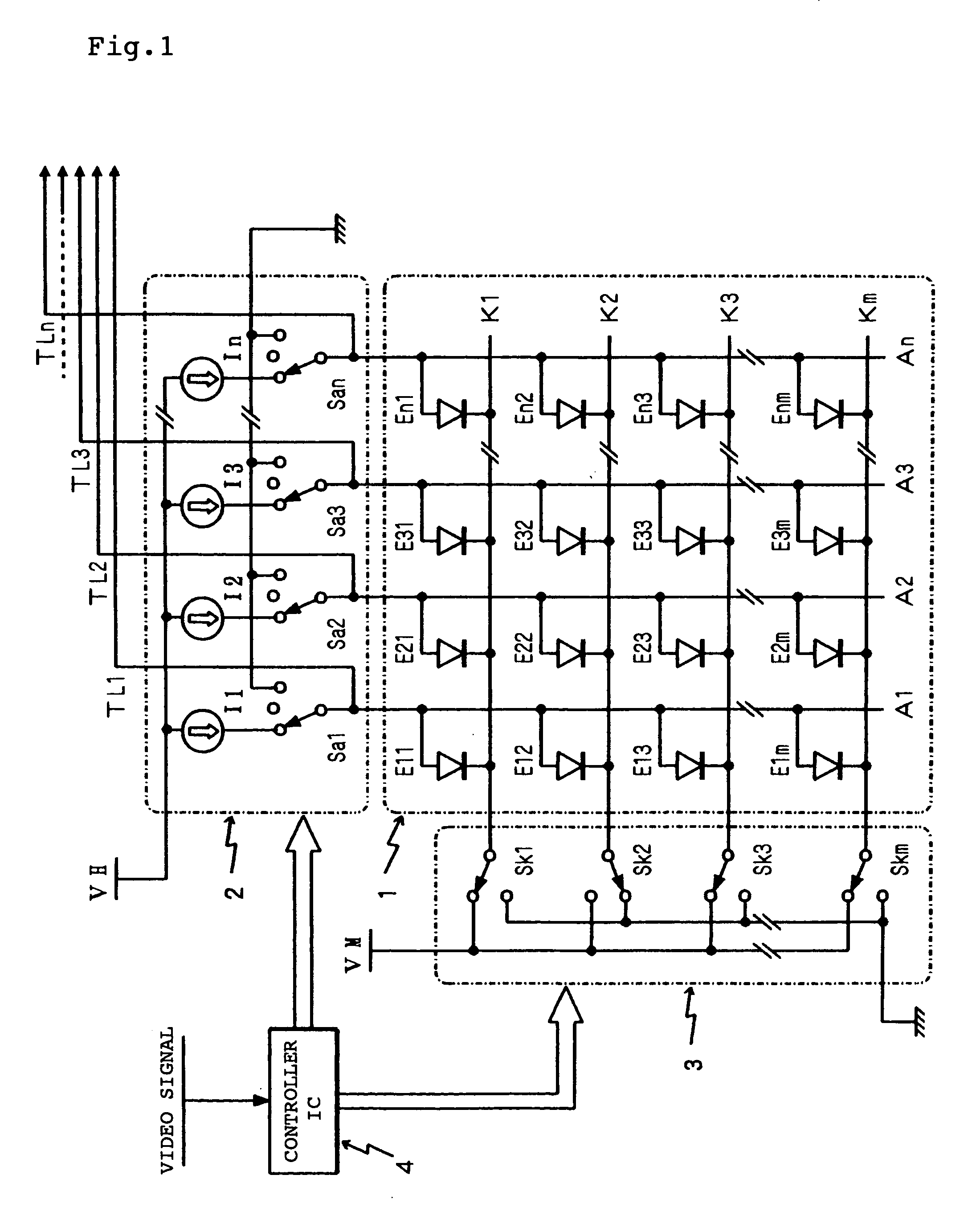
[0016] A self light emitting display module according to the present invention will be described below with reference to the embodiment shown in the drawings. In the self light emitting display module according to the present invention, provided are a self light emitting display unit composed of a light emitting display panel in which a large number of self light emitting elements are arranged as pixels in a matrix pattern and drive means for selectively driving and lighting the respective light emitting elements in this light emitting display panel, and further provided are a trouble detection means for detecting trouble of a self light emitting display unit and a memory means for storing detection results of the trouble detection means. In the embodiments explained below, shown is an example in which organic EL elements in which an organic material is employed in a light emitting layer are adopted as the self light emitting elements.

[0017] The organic EL element can be electrical...


PUM


Abstract

In a detection mode, a reverse bias voltage VM is applied to any one of scan lines K1-Km arranged in a light emitting display panel 1. The electrical potentials generated at respective data lines A1-An of this time are supplied to potential determination means J1-Jn. In the potential determination means J1-Jn, the electrical potentials generated at the respective data lines A1-An are supplied to switching elements Q31-Q3n via transfer switches Q11-Q1n. When the electrical potentials are the threshold voltages of the switching elements Q31-Q3n or greater, the outputs of comparators CP1-CPn are inverted, and the states of this time are latched in latch circuits LC1-LCn to be stored in a data register 11. By data stored in the data register 11, it is determined whether or not a defect has occurred in pixels of the display panel, and the location thereof is also determined.

Description

BACKGROUND OF THE INVENTION [0001] 1. Field of the Invention [0002] The present invention relates to a self light emitting display module provided with a light emitting display panel in which for example organic EL (electroluminescent) elements are employed for pixels as self light emitting elements and drive means to drive and light this panel, and particularly to a self light emitting display module having a function that can generally inspect a state in which a defect is occurring in the self light emitting elements in the light emitting display panel and an inspection method of a defect state in the same module. [0003] 2. Description of the Related Art [0004] A display has been installed in many of electronic equipment or the like which have been provided presently, and this display has been necessary and indispensable as a man-machine interface of equipment supporting information-oriented society. In a case where the above-mentioned display is employed in a field in which there...

Claims


Application Information

Patent Timeline
IPC IPC(8): G01R31/00G01R31/28G09F9/00G09G3/00G09G3/20G09G3/30G09G3/32H01L51/50H05B33/12H05B33/14
CPCG09G3/006G09G3/2011G09G2330/12G09G3/3275G09G2330/10G09G3/3216
Inventor SATO, HIROYUKIGOTO, TAKASHI
Owner TOHOKU PIONEER CORP
Why Eureka
Try Eureka