Display device

Active Publication Date: 2005-09-29
SAMSUNG DISPLAY CO LTD +1
View PDF6 Cites 16 Cited by
  • Summary
  • Abstract
  • Description
  • Claims
  • Application Information

AI Technical Summary

Benefits of technology

[0008] The present invention makes it possible to improve the image quality of moving picture display without having to convert input display data to generate a black display indication, change the pixel configuration of a self-luminous element based display, or furnish a new switch for inserting a black display indication.
[0009] Si

Problems solved by technology

Thus, the image quality of moving pictures dete

Method used


Image

  • Display device
  • Display device
  • Display device

Examples


Example

[0021] A first embodiment of the present invention will now be described in detail with reference to the accompanying drawings.

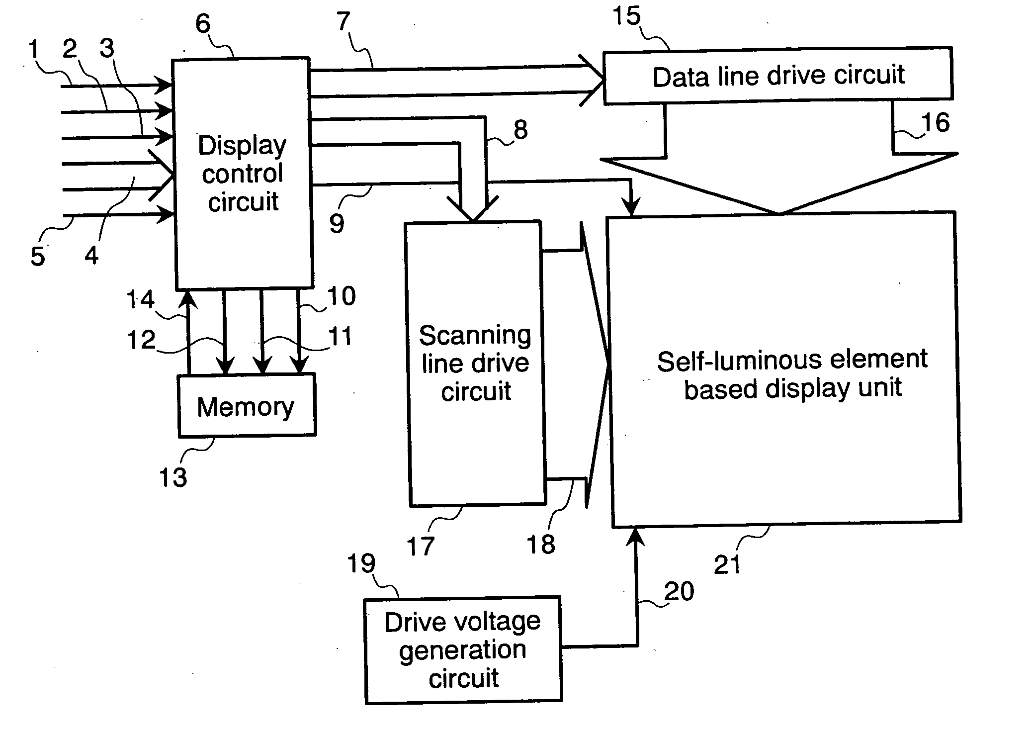
[0022]FIG. 1 shows an example of a self-luminous element based display device according to the first embodiment of the present invention. In FIG. 1, the reference numeral 1 denotes a vertical sync signal; 2, a horizontal sync signal; 3, a data enable signal; 4, display data (either analog or digital); and 5, a sync clock. The vertical sync signal 1 is a 1-screen period (1-frame period) signal. The horizontal sync signal 2 is a 1-horizontal period signal. The data enable signal 3 is a signal that indicates a period during which display data 4 is valid (display validity period). All signals are entered in synchronism with the sync clock 5.

[0023] In the present embodiment, it is assumed that the display data 4 for one screenful is sequentially transferred by a raster scan method, beginning with a pixel in the upper left corner of the screen, and that one pixe...

Example

[0088] A second embodiment of the present invention will now be described with reference to the accompanying drawings. FIG. 9 shows an example of a self-luminous element based display device according to the second embodiment of the present invention.

[0089] Like elements in FIGS. 1 and 9 are designated by like reference numerals and will not be described herein because they are identical with the counterparts described in conjunction with the first embodiment. The reference numeral 126 denotes a display control circuit, and the reference numeral 127 denotes a video-ready sweep signal. The display control circuit 126 generates the video-ready sweep signal 127, which is a sweep signal suitable for input video. The ensuing explanation assumes that there are two types of input video: moving picture and still picture. In the other respects, the display control operation is the same as described in conjunction with the first embodiment.

[0090]FIG. 10 illustrates how the display control c...


PUM


Abstract

A display control circuit and a display unit are provided. The display control circuit generates a sweep signal that is at a fixed voltage level for an arbitrary period. The display unit compares the magnitude of a signal voltage that is written by a data line drive circuit in accordance with display data and the magnitude of the sweep signal generated by the display control circuit, and exercises illumination/nonillumination control in accordance with the comparison result.

Description

CROSS REFERENCE TO RELATED APPLICATION [0001] This application relates to and claims priority from Japanese Patent Application Serial No. 2004-88468 filed on Mar. 25, 2004, the entire disclosure of which is incorporated herein by reference. BACKGROUND OF THE INVENTION [0002] The present invention relates to a display device that is capable of controlling its luminance in accordance with the amount of current applied to a display element or the duration of illumination, and more particularly to a display device that drives a light-emitting diode (LED), organic EL (organic electroluminescence) element, or other self-luminous display element. [0003] A self-luminous element based illumination control method disclosed by U.S. patent application Publication No. 2002 / 196213 (JP-A-2003-5709) switches between a data write period and drive period in a data write line and provides a drive period in the other lines. This patent document states that the waveform generated by a drive signal line ...

Claims


Application Information

Patent Timeline
IPC IPC(8): G09G3/20H01L51/50G09G3/30G09G3/32G09G3/36H05B33/14
CPCG09G3/2011G09G3/3258G09G3/3266G09G3/3275G09G2300/0809G09G2360/18G09G2300/0842G09G2300/0861G09G2310/0251G09G2320/0257G09G2320/0261G09G2300/0819G09G3/20G09G3/36G09G3/30G09G3/32
Inventor KASAI, NARUHIKOAWAKURA, HIROKISATOU, TOSHIHIROAKIMOTO, HAJIME
Owner SAMSUNG DISPLAY CO LTD
Why Eureka
Try Eureka