Mini-camera with an adjustable structure

Inactive Publication Date: 2005-09-29
ZIPPY TECH
View PDF5 Cites 55 Cited by
  • Summary
  • Abstract
  • Description
  • Claims
  • Application Information

AI Technical Summary

Benefits of technology

[0006] In order to achieve the foregoing objects, the present invention provides a mini-camera with an adjustable structure. It is not required to use an extra tool to loosen the screwing element and can directly adjust the view angle of a camera lens. The mini-camera with adjustable structure mainly includes a camera body, a support and at least one limiting element disposed in-between the camera body and support.

Problems solved by technology

However, the thickness and strength of the upright member itself is not enough, and therefore difficult to calculate the force sufficient to fix the body.
The screwing element is often over tightened, Which can damage the electronics.
If the screwing element is held too loose then the camera body can shake e

Method used


Image

  • Mini-camera with an adjustable structure
  • Mini-camera with an adjustable structure
  • Mini-camera with an adjustable structure

Examples


Example

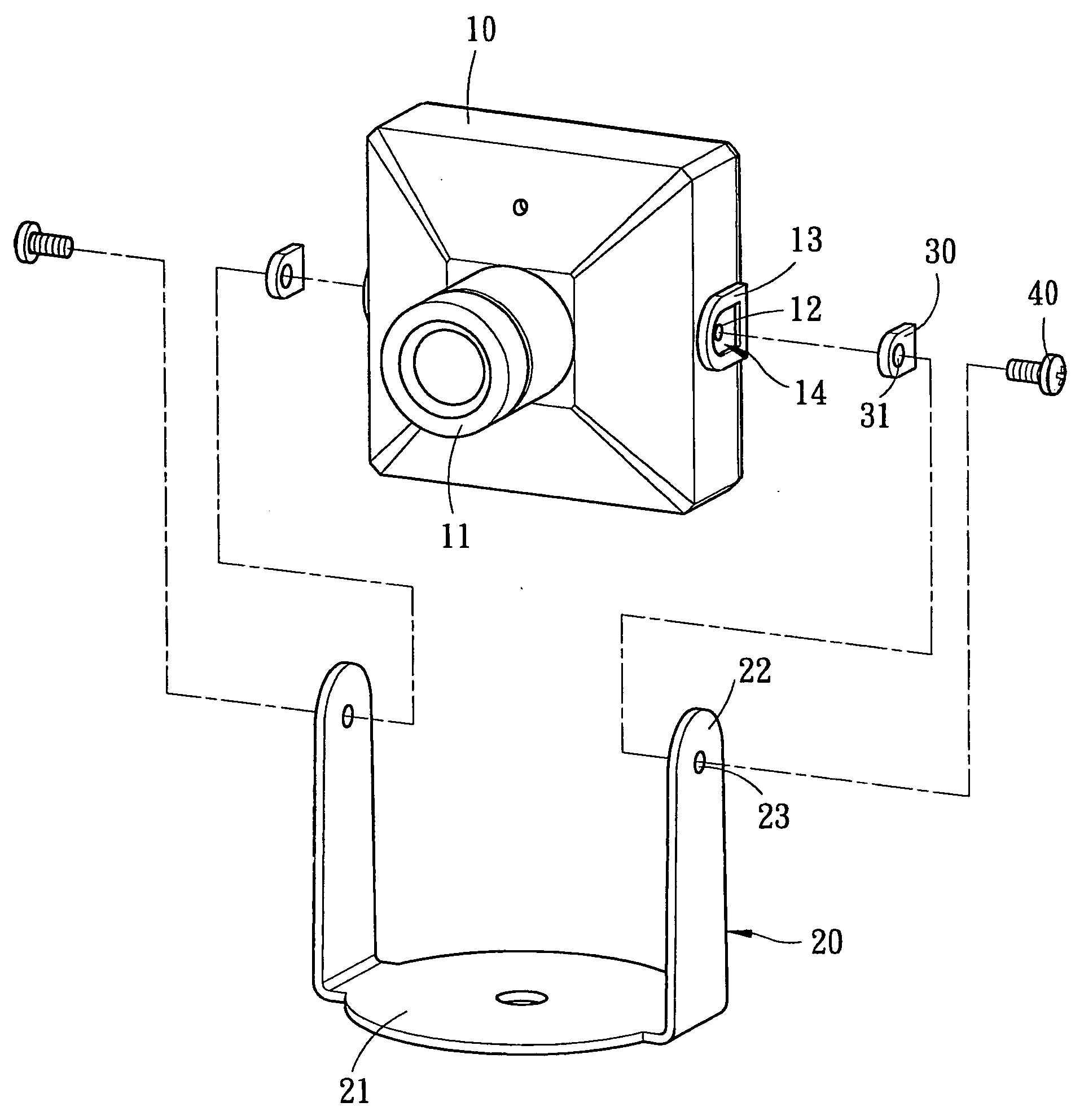
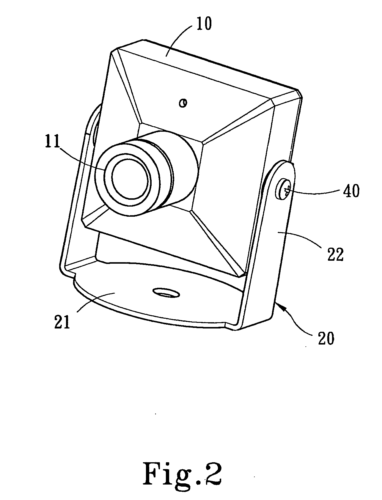
[0013] Referring to FIGS. 2 and 3, they depict a perspective schematic view and a perspective exploded schematic view of a mini-camera with an adjusting structure of the present invention. The mini-camera mainly includes a camera body 10, a support 20 and a limiting element 30 disposed at a connection between the camera body 10 and support 20. The camera body 10 is a pinhole type camera, but it is not used to limit the present invention. The camera body 10 has a camera lens 11 having two positioning holes 12 t disposed either side of the camera body 10. The positioning hole 12 can be a screw hole. A receiving area 14 is surrounded by a frame 13 disposed around the positioning hole 12 of the camera body 10 for inserting the limiting element 30. The support 20 holds the camera body 10, and further the camera body 10 can be rotated and adjusted relative to the support. The support 20 has a base 21 mounted on a body (such as a wall) for installation. Two branches 22 are upward expanded ...


PUM


Abstract

A mini-camera with an adjustable structure mainly includes a camera body, a support and at least one limiting element disposed at a connection between the camera body and the support. The limiting element provides the camera body with enough friction for adjusting the viewing angle of a camera lens relative to the support. A user can step-less adjust the view angle of the camera lens of the camera body, the user doesn't need disassemble the camera body or the support, and further the user cannot damage the connection between the camera body and the support for maintaining the outside beauty of the mini-camera.

Description

FIELD OF THE INVENTION [0001] The present invention relates to a mini-camera with an adjustable structure, and more particularly to a mini-camera applied in a pinhole type camera having an adjustable structure for a step-less adjustment for the viewing angle of a camera lens. BACKGROUND OF THE INVENTION [0002] The standard positioning mode for a pinhole type mini-camera is shown in FIG. 1. The pinhole type mini-camera mainly includes a camera body and supporting stand. The camera body is provided with two screw holes disposed on two sides thereof, and the bottom of the support is a connecting portion that is mounted on a body to be installed. Two upright members extend from two sides of the connecting portion. Each upright member is provided with a hole that corresponds to the above-mentioned screw hole. The camera body is installed on the support by utilizing a screwing element to mount into the screw hole. However, the screwing element has the following disadvantages: [0003] (1). ...

Claims


Application Information

Patent Timeline
IPC IPC(8): F16M11/10H04N5/225
CPCH04N5/2252F16M11/10H04N23/51
Inventor SU, TSUI-JUNGLEE, KING-LONGWU, WEN-HONG
Owner ZIPPY TECH
Why Eureka
Try Eureka