Portable lantern and related method of using it

a portable lantern and light source technology, applied in the field of lanterns, can solve the problems of inefficient direct light in all radial directions of current portable lanterns, and achieve the effect of efficient direct light emission and efficient space us

Inactive Publication Date: 2005-09-29
BRINKMANN AG
View PDF10 Cites 11 Cited by
  • Summary
  • Abstract
  • Description
  • Claims
  • Application Information

AI Technical Summary

Benefits of technology

[0008] The present invention resides in a portable lantern and related method of use that provide for more efficient use of space when a fuel tank is not coupled to the lantern's fuel delivery system, and more efficiently directs the light emitted from the portable lantern. Mor

Problems solved by technology

Accordingly, current portable lanterns ineffi

Method used


Image

  • Portable lantern and related method of using it
  • Portable lantern and related method of using it
  • Portable lantern and related method of using it

Examples


Embodiment Construction

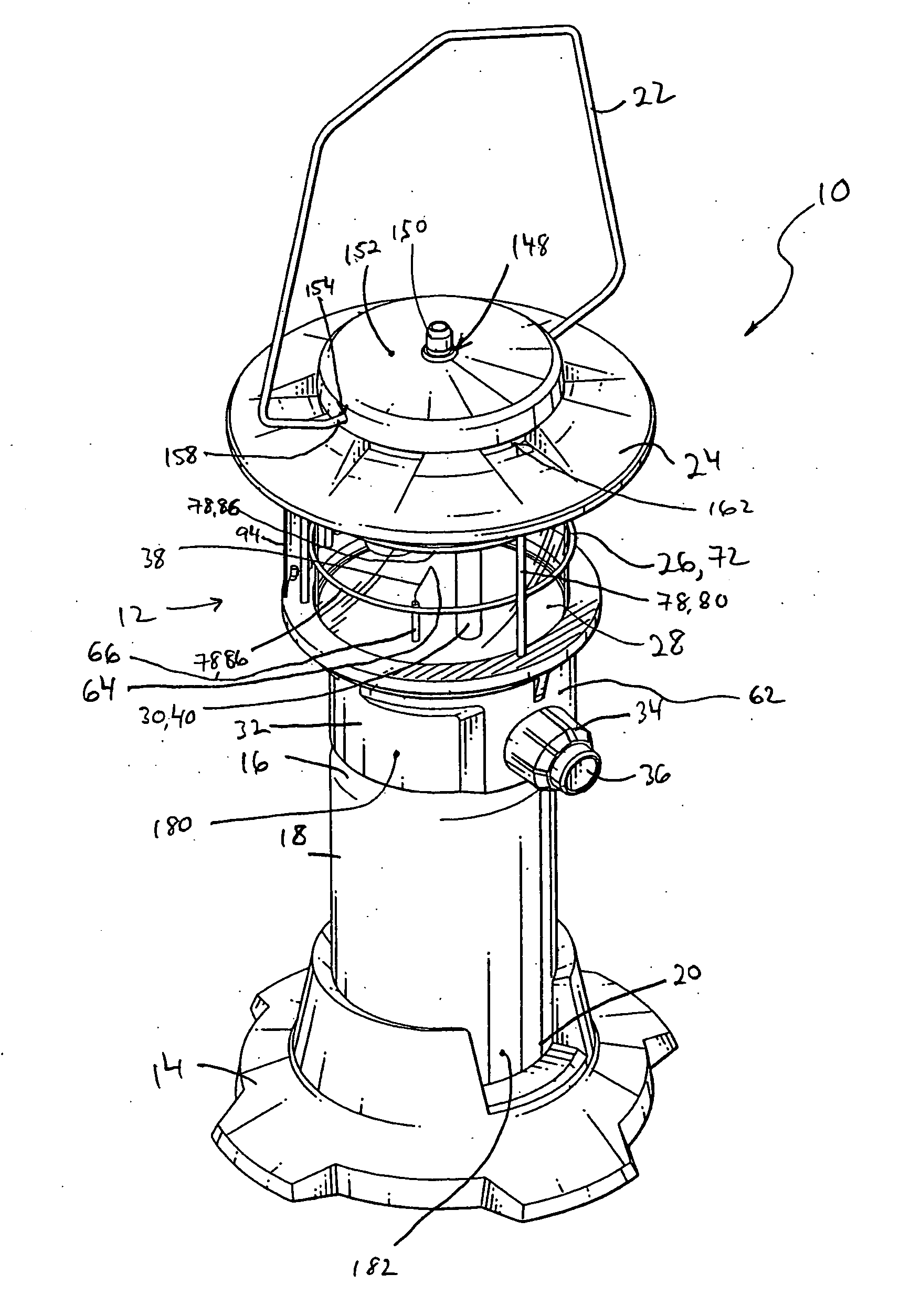
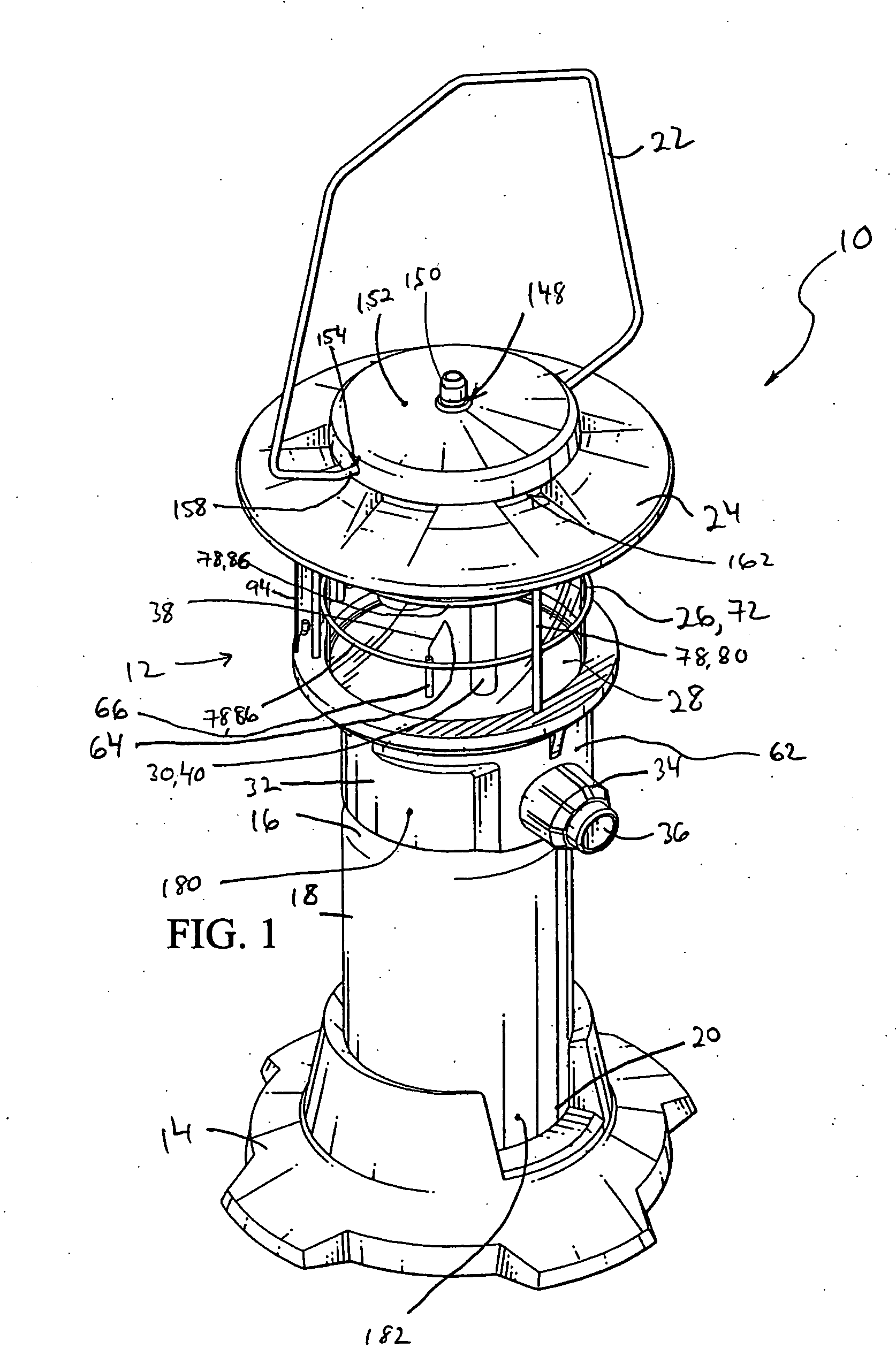
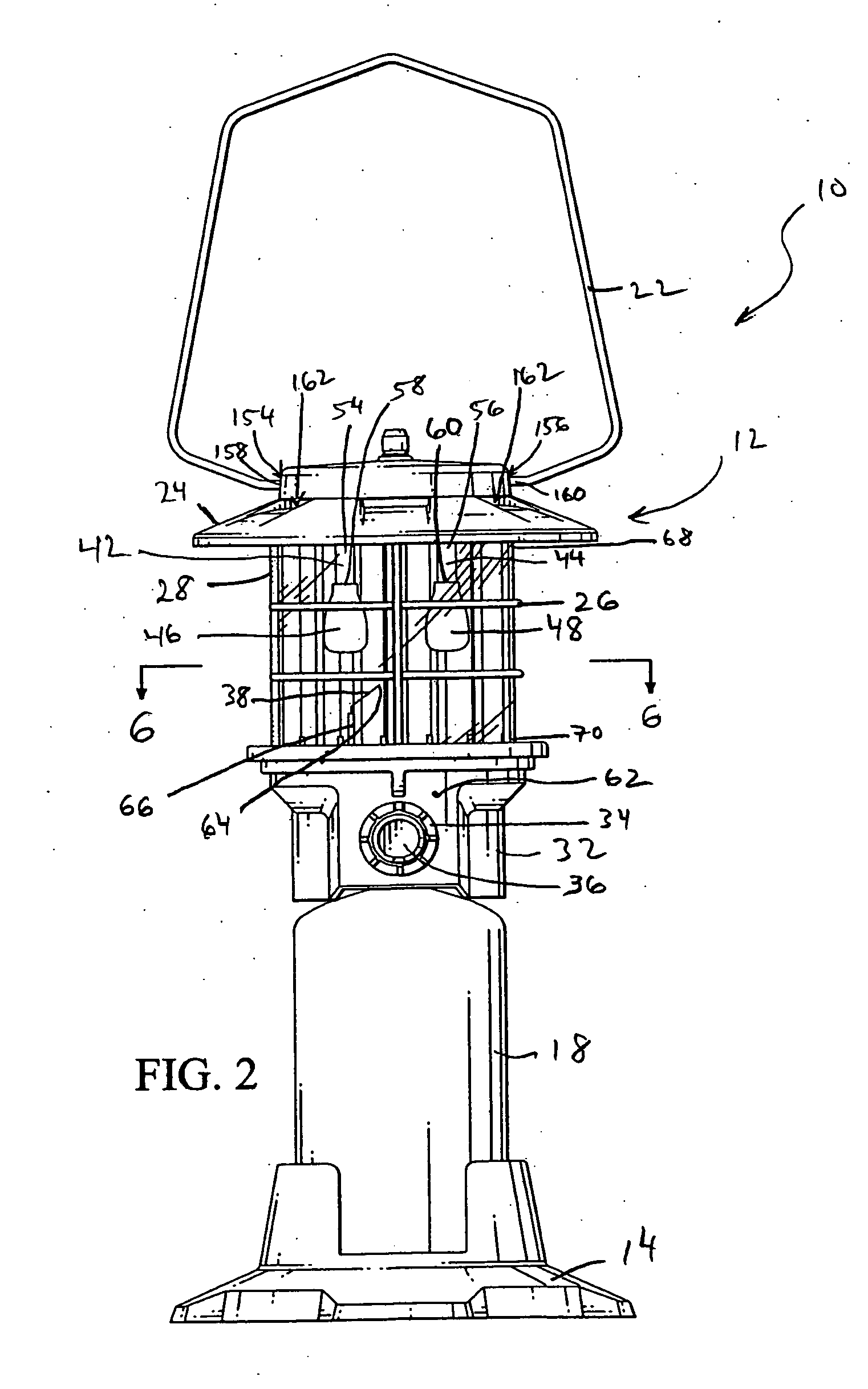
[0036] With reference now to the illustrative drawings, and particularly to FIGS. 1 and 2, there is shown a portable lantern 10, which includes a housing 12 and a base 14. One end 16 of a fuel tank 18 can be coupled to the housing, and an opposite end 20 of the fuel tank can be coupled to the base, as discussed below. The fuel tank can contain any of various types of fuel, e.g., liquid propane or butane. The housing includes a lantern handle 22, a housing top 24, a shield assembly 26, a globe 28, a fuel delivery and ignition system 30, and a housing bottom 32.

[0037] As shown in FIGS. 1-3, the housing 12 is generally cylindrical in shape, as defined by the housing top 24, shield assembly 26, globe 28, and housing bottom 32. However, it should be understood that the general shape of the housing can be other than cylindrical, e.g., the general shape of the housing can be such that a cross section of the housing is generally square or elliptical in shape.

[0038] The fuel delivery and i...


PUM


Abstract

A lantern that includes a housing and a reflector assembly having at least one reflector panel that is pivotably coupled to the housing and configured to reflect light produced by the lantern. The housing is configured to interface with a fuel tank and a base. The base is separate from the housing and configured both to interface with the housing when the housing is not interfaced with the fuel tank, and to interface with the fuel tank when the housing also is interfaced with the fuel tank.

Description

CROSS-REFERENCE TO RELATED APPLICATION [0001] Priority is claimed under 35 U.S.C. § 119(e) to U.S. Provisional Patent Application No. 60 / 556,810, filed on Mar. 25, 2004, entitled: “PORTABLE LANTERN AND RELATED METHOD OF USING IT,” by Randall L. May, Gary P. Israel, and Robert J. Gross, which application is incorporated by reference herein.BACKGROUND OF THE INVENTION [0002] 1. Field of the Invention [0003] The invention relates generally to the field of lanterns. More specifically, the invention relates to portable, fuel-burning lanterns. [0004] 2. Description of the Related Art [0005] Typically, portable lanterns are used in instances where light is required in a site remote from an electrical connection, e.g., a camp site. Portable lanterns include a fuel storage tank (“fuel tank”) and a fuel delivery system configured within a lantern housing, which defines the outward shape of the portable lantern. The fuel delivery system couples to the fuel tank and includes a burner, at the ou...

Claims


Application Information

Patent Timeline
IPC IPC(8): F21H1/00F21L19/00F21V11/08F21V14/04F21V17/02F21V37/00
CPCF21L19/00F21V11/08F21V37/0062F21V17/02F21V14/04
Inventor MAY, RANDALL L.ISRAEL, GARY P.
Owner BRINKMANN AG
Why Eureka
Try Eureka