Paint mixer

a paint mixer and paint technology, applied in the field of paint mixers, can solve the problems of contaminating the mixer and possibly the environment of the mixer, unintended partial or full release of the coating container, and damage to the coating container and possibly the mixer,

Active Publication Date: 2005-09-29
RED DEVIL EQUIP
View PDF22 Cites 38 Cited by
  • Summary
  • Abstract
  • Description
  • Claims
  • Application Information

AI Technical Summary

Problems solved by technology

While such an approach was generally satisfactory, the lead screw was prone to unscrewing during mixing, resulting in unintended partial or full release of the coating container, with consequent damage to the coating container and possibly the mixer.
If the coating con

Method used


Image

  • Paint mixer
  • Paint mixer
  • Paint mixer

Examples


Embodiment Construction

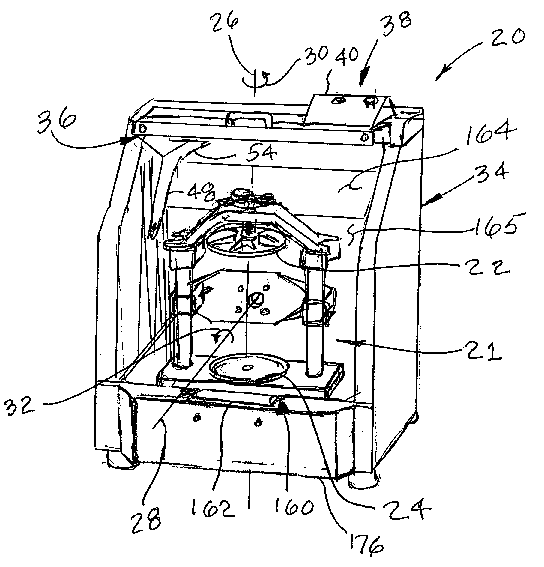
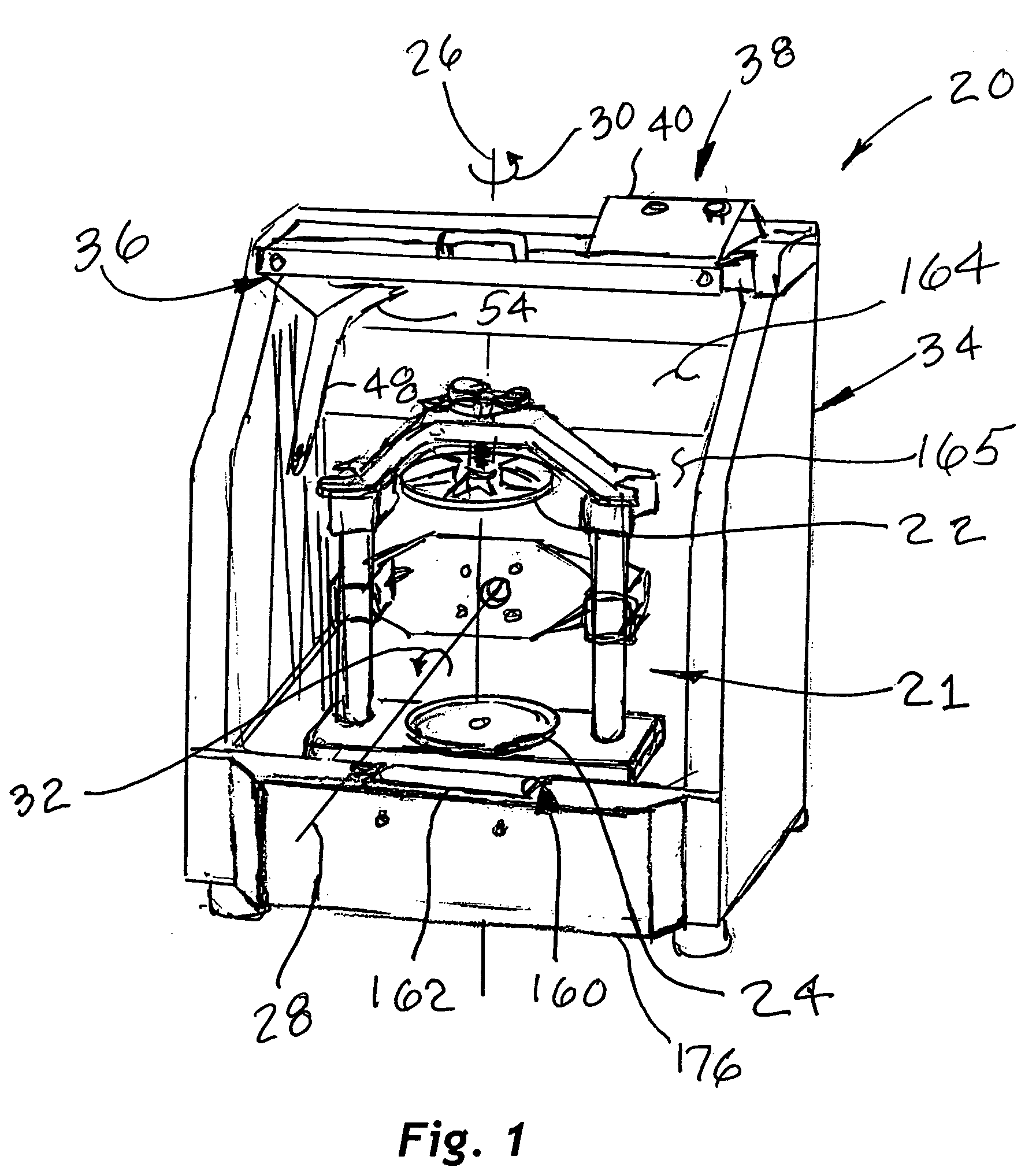
[0030] Referring to the Figures, and most particularly to FIGS. 1 and 2, an improved paint mixer 20 may be seen. Mixer 20 is of the type having a clamping mechanism 21 which includes a rotatable frame 23 and a pair of opposed plates 22 and 24 sized and spaced to receive and clamp a conventional 5 gallon container of paint or similar coating material. In operation, mixer 20 will rotate the container about a pair of axes 26 and 28 as indicated by arrows 30 and 32. Mixer 20 has an enclosure 34 with a door 36, shown in an OPEN position in FIGS. 1 and 2. Suitable controls 38 may be mounted on a control panel 40 to start, stop and control the operation (e.g., timing) of the mixer 20.

[0031] As may be seen most clearly in FIG. 2, mixer 20 may have a single pivot point system 42 on each side (only one of which is shown) which improves alignment and durability of the door 36. System 42 includes a mounting pad 44 secured to the enclosure 34, and a boss 46 for pivotably receiving and supportin...


PUM


Abstract

An improved paint mixer of the type rotating a paint container about a tumbling axis and a perpendicular spin axis, the improvements of a clamp assembly and lock, splash guards protecting a range-of-travel of upright clamp portions, low friction guide plates, an adjustable height strike plate and roller, a rigid gear assembly, an offset in the clamp to return the paint container to an upright position after mixing, and a relief in a raised portion on a lower plate of the clamp for assisting loading and unloading of the paint container.

Description

BACKGROUND OF THE INVENTION [0001] The present invention relates to the field of paint mixers of the type for mixing paint and related liquid coatings in conventional containers in the range of about 5 gallons or about 20 liters. More particularly, the present invention relates to such mixers which utilize gyroscopic mixing motion while the coating container is clamped between a pair of opposed plates. It is to be understood that such mixers are suitable for mixing coatings in the range of about 1 gallon to about 5 gallons (or the metric equivalent), and may be utilized to mix coatings in other than cylindrical containers, including, but not limited to so-called “square” containers, particularly when adapters or special shaped container holders are used. [0002] In the past, one such mixer clamped the coating container by advancing one plate towards the other using a lead screw rotated by a hand wheel. While such an approach was generally satisfactory, the lead screw was prone to uns...

Claims


Application Information

Patent Timeline
IPC IPC(8): B01F9/00B01F11/00B01F15/00
CPCB01F9/0014Y10S366/605B01F2215/005B01F15/00753B01F29/30B01F35/423B01F2101/30
Inventor MIDAS, THOMAS J.HARROLD, BRENT THOMASGRAN, WILLIAM O.
Owner RED DEVIL EQUIP
Why Eureka
Try Eureka