
Electronic enclosure

a technology for enclosures and electronic devices, applied in the direction of electrical apparatus casings/cabinets/drawers, cable installation in cable chambers, coupling device connections, etc., can solve the problems of difficult installation and maintenance of existing pedestal enclosures, difficult to add, replace or update wires, cables or other equipment in the pedestal enclosure, etc., to prevent the effect of disengagement of the cover

Inactive Publication Date: 2005-09-29
CHARLES INDS
View PDF19 Cites 31 Cited by
  • Summary
  • Abstract
  • Description
  • Claims
  • Application Information

AI Technical Summary

Benefits of technology

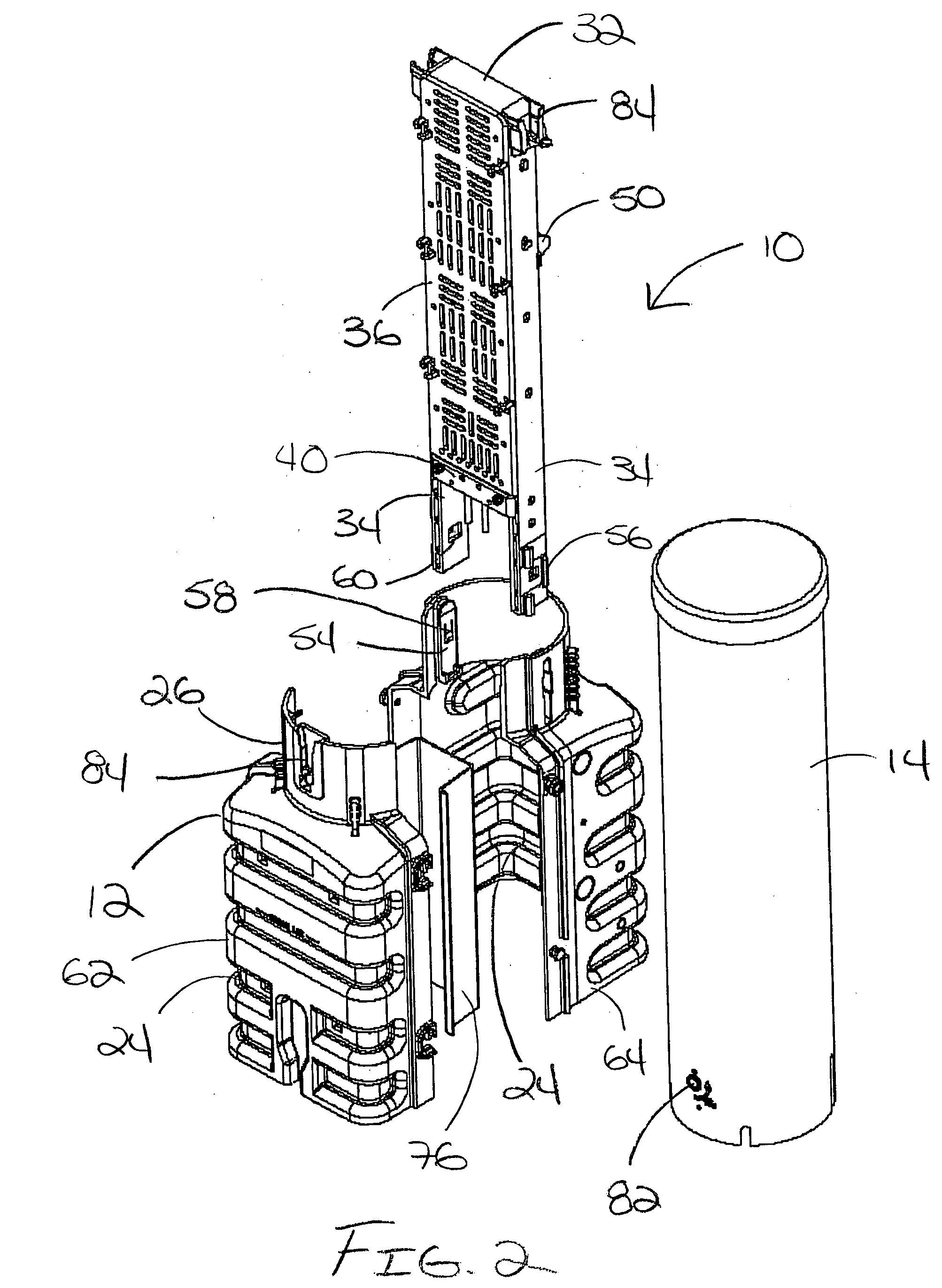
[0005] The invention provides a pedestal enclosure for electronic components. The pedestal enclosure includes a base section and a cover engageable with the base section so as to define an interior space. A bracket system supported on the base section and arranged in the interior space. A lock mechanism arranged near the top or near the bottom of the cover. The lock mechanism includes a latch supported in a lock housing for movement between locked and unlocked positions. A first lock receptacle arranged on the base section for receiving the lock mechanism when the cover is engaged with the base section and the lock mechanism is arranged near the bottom of the cover and a second lock receptacle located on the bracket system for receiving the lock mechanism when the cover is engaged with the base section and the lock mechanism is arranged near the top of the cover. Each of the first and second lock receptacles defines a pocket for supporting the lock housing and is engageable with the latch when the latch is in the locked position so as to prevent disengagement of the cover from the base section.

Problems solved by technology

Unfortunately, many existing pedestal enclosures are difficult to install and maintain.
Many pedestal enclosures also are not readily adaptable to different field conditions and / or the requirements of different applications.
Moreover, with many pedestal enclosures, it can be difficult to add, replace or update the wires, cable or other equipment in the pedestal enclosure once it is installed in the field.
Similarly, components of the pedestal enclosure that are damaged or require upgrading such as wire channels or the bracket system can be difficult to replace once the pedestal is installed in the field.
The locking systems of many pedestal enclosures are also awkward to operate.
In addition, some pedestal enclosures do not provide the necessary protection against impacts, fires and the environment.

Method used


Image

  • Electronic enclosure
  • Electronic enclosure
  • Electronic enclosure

Examples


Embodiment Construction

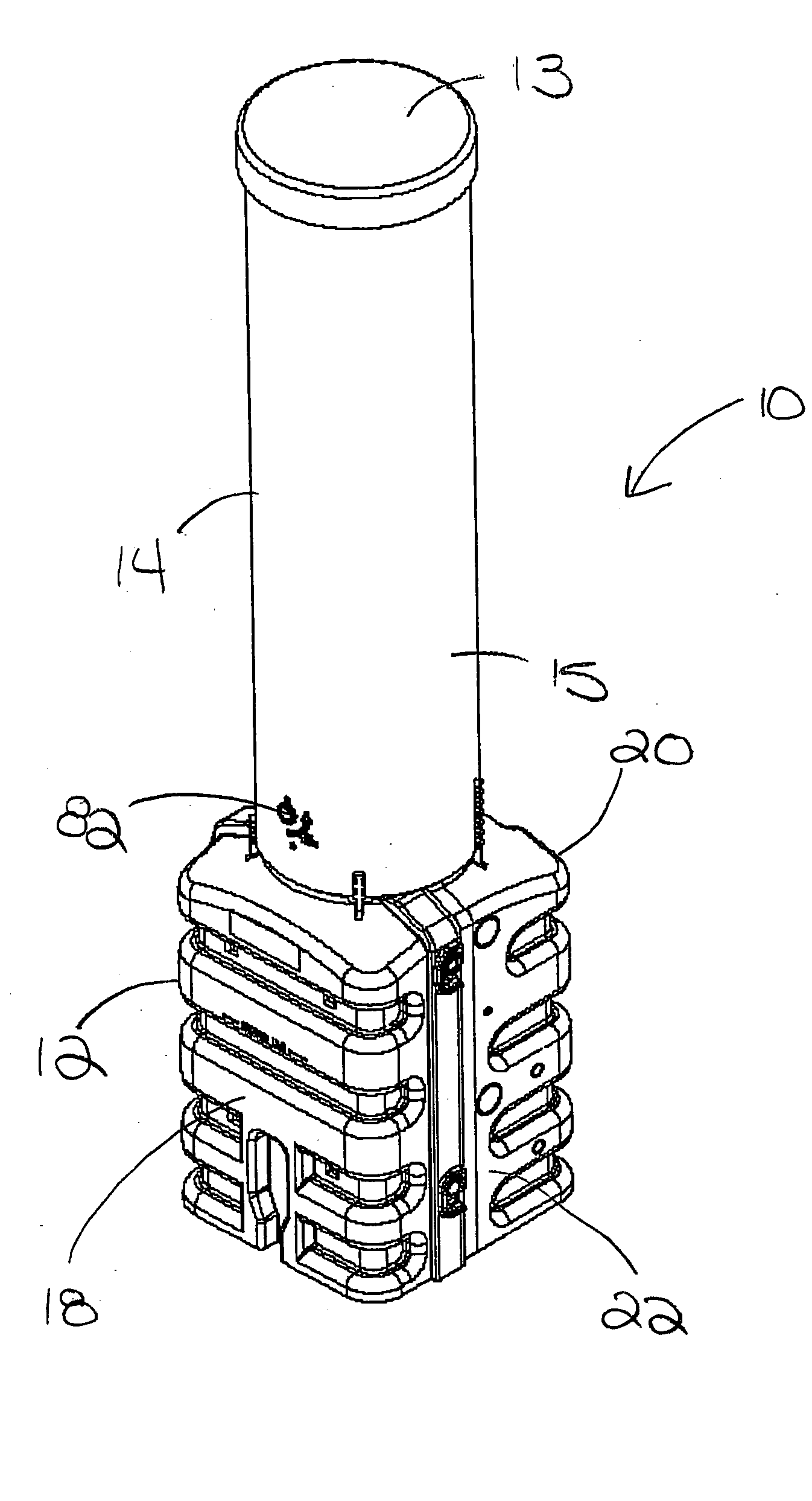
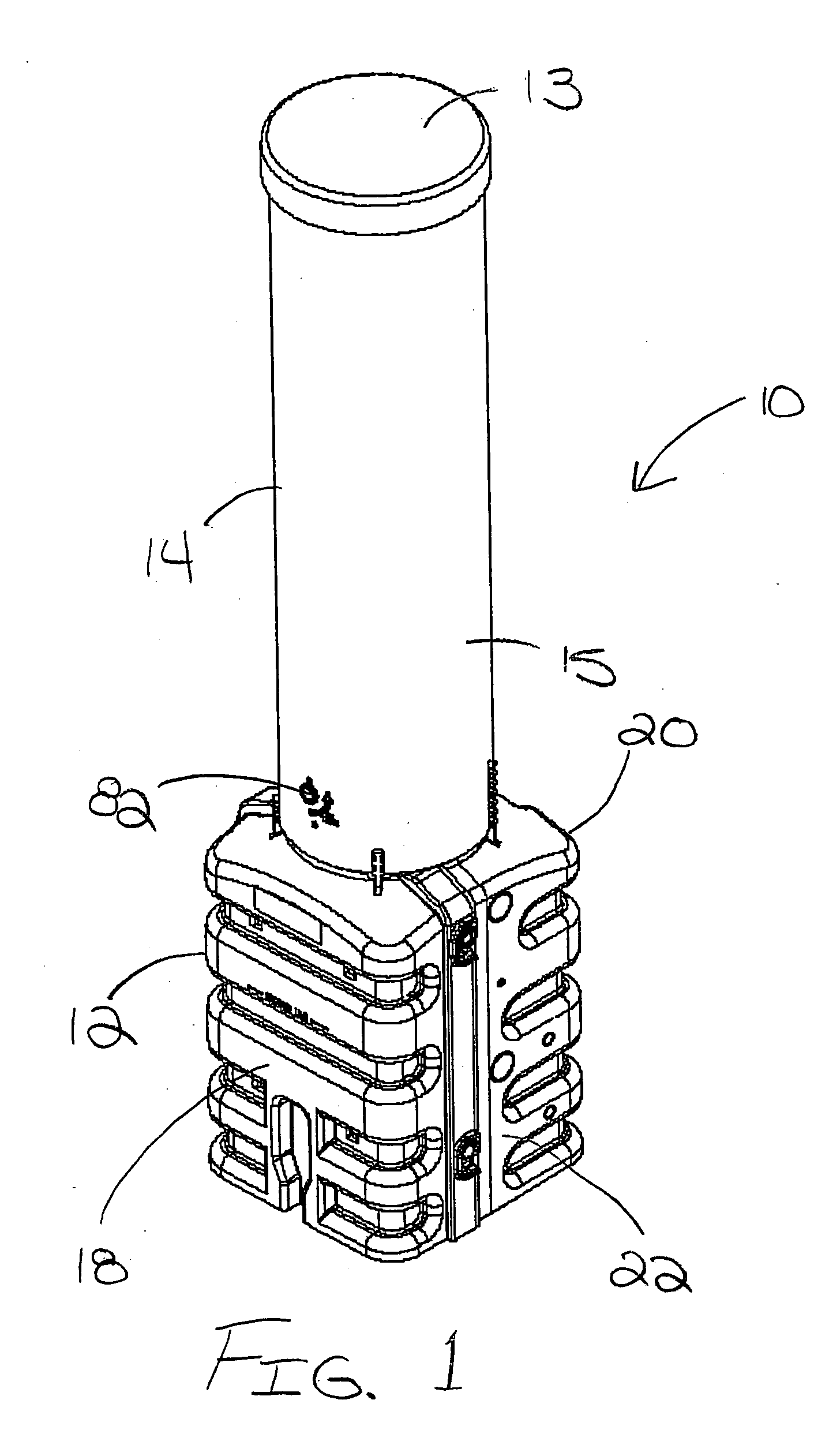
[0027] Referring now to FIGS. 1 and 2 of the drawings, there is illustrated an exemplary pedestal enclosure 10 constructed in accordance with the teachings of the present invention. The illustrated pedestal enclosure 10 includes a base section 12 and a cover or dome 14. The cover 14 nests in a telescoping fashion over the base section 12 so as to define an interior space within the pedestal enclosure 10. This interior space can be used to house electronic equipment such as used in telecommunications, cable television or power transmission applications. The cover of the illustrated pedestal enclosure 10 is cylindrical in shape including a top or end wall 13 and a sidewall 15. As will be appreciated by those skilled in the art, the present invention is not limited to any particular pedestal enclosure size or configuration. Moreover, while the present invention is discussed in the context of telecommunication systems, the present invention is not limited to a pedestal enclosure for hou...


PUM


Abstract

A pedestal enclosure for electronic components is provided. The pedestal enclosure includes a base section and a cover engageable with the base section so as to define an interior space. The base section has a generally rectangular configuration and having a plurality of longitudinally extending channels formed therein such that the base section is substantially self-supporting in the ground. The cover has a generally cylindrical configuration and is engageable with a cylindrical neck on the base section so as to define an interior space. A bracket system is supported on the base section and arranged in the interior space. The bracket system includes a pair of legs. The base section comprises front and rear housing sections that can be selectively assembled together and split apart without removal of the bracket system. A lock mechanism is arranged near the top or near the bottom of the cover. A first lock receptacle is arranged on the base section for receiving the lock mechanism when the cover is engaged with the base section and the lock mechanism is arranged near the bottom of the cover and a second lock receptacle is arranged on the bracket system for receiving the lock mechanism when the cover is engaged with the base section and the lock mechanism is arranged near the top of the cover. A splice bar is pivotably supported between the legs of the bracket system for movement between an locked position wherein a hook at each end of the splice bar engages a respective one of the legs of the bracket system and an unlocked position wherein the splice bar is disengaged from the legs of the bracket system.

Description

FIELD OF THE INVENTION [0001] This invention pertains to electronic enclosures and, more particular, to an electronics enclosure with improved flexibility and ease of use. BACKGROUND OF THE INVENTION [0002] Pedestal style electronics enclosures are used in telecommunications systems to house splices or terminal connections between service wires or distribution wires and buried telephone cables. Such pedestal enclosures can also be used to house connections to other types of buried utility cables such as for cable television, fiber optics or power distribution. A bracket system is generally provided on the interior of a pedestal enclosure to help arrange and support the cabling and various connections housed in the pedestal enclosure. Since pedestal enclosures are located outdoors, they must be substantially weather tight in order to protect the electronic connections from adverse environmental conditions such as wind, rain, snow and flooding. The pedestal enclosures also have to be ...

Claims


Application Information

Patent Timeline
Patent Type & Authority Applications(United States)
IPC IPC(8): H01J5/00H02G9/10
CPCH02G9/10
Inventor HARWOOD, WALTER
Owner CHARLES INDS
Learn More